3D Printed and Scratchbuilt Space Shuttle Orbiter
OH LOOK A VIDEO

So, after building the Enterprise from PVC pipe, plumbing parts, MDF and junk, I thought I'd try another.
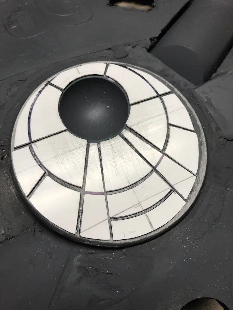
All of these projects tend to start with the realisation that something looks like something else, and the Falcon has been no different. My starting point for this ship was this PVC vent cowling...

...which is very obviously a Falcon cockpit in disguise.
I didn't use blueprints for the Enterprise, because it was a basic enough shape to build from measurements alone, but the Falcon is a bit more complex and detailed. Googled some diagrams. Scaled them appropriately. Printed them out. Stuck a billion pages together. Yay, blueprints. (If these are your drawings and you don't mind me using them, then thank you! If they're yours and you do mind, then, um, sorry. Whoops?)
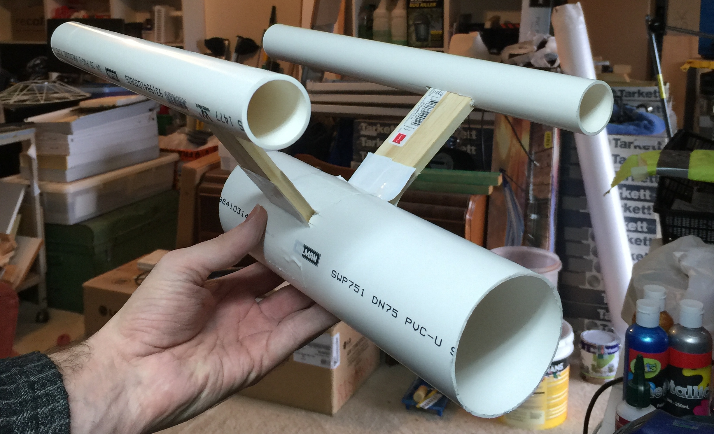
So the plan is PVC pipes for the pipe-shaped bits and MDF for the flat bits, then kinda make the rest up as I go along.

Blueprints with measurements and "cockpit" for scale.

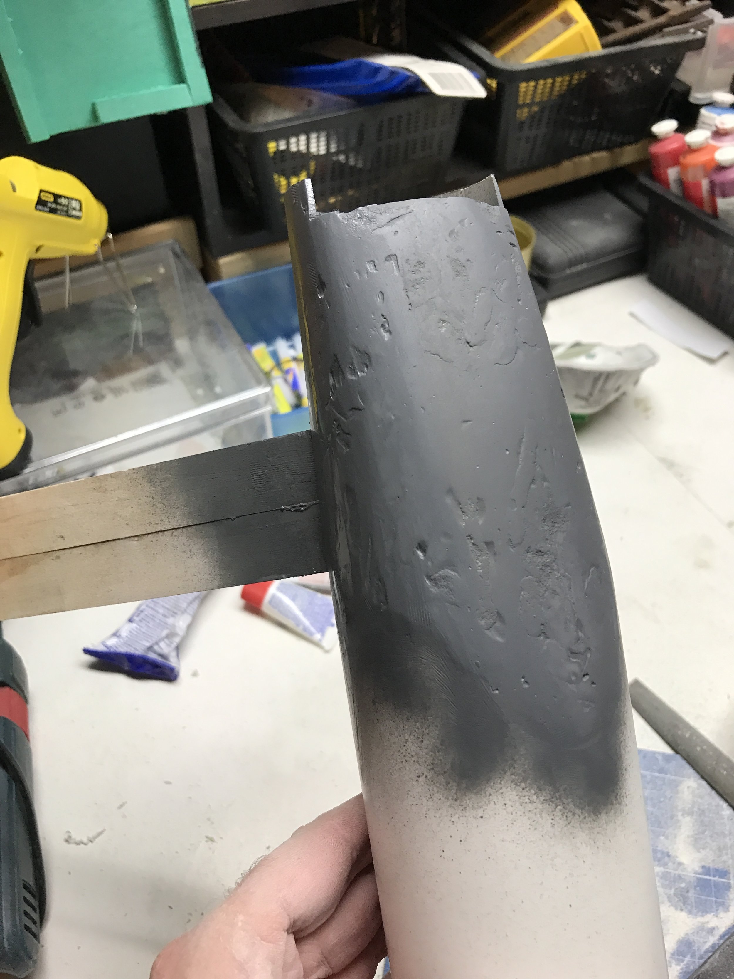
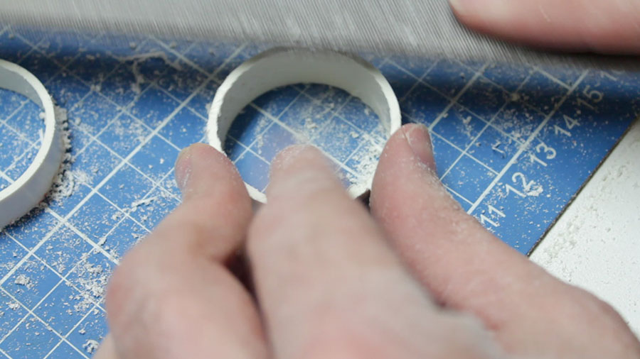
Main shape is cut from MDF. Hull is two MDF sheets with some bits of 20mm timber in between like a sandwich. Had a heck of a time getting the "slot" that the tube goes into to work properly, but after a lot of filing and cutting and swearing, it slots in nicely.
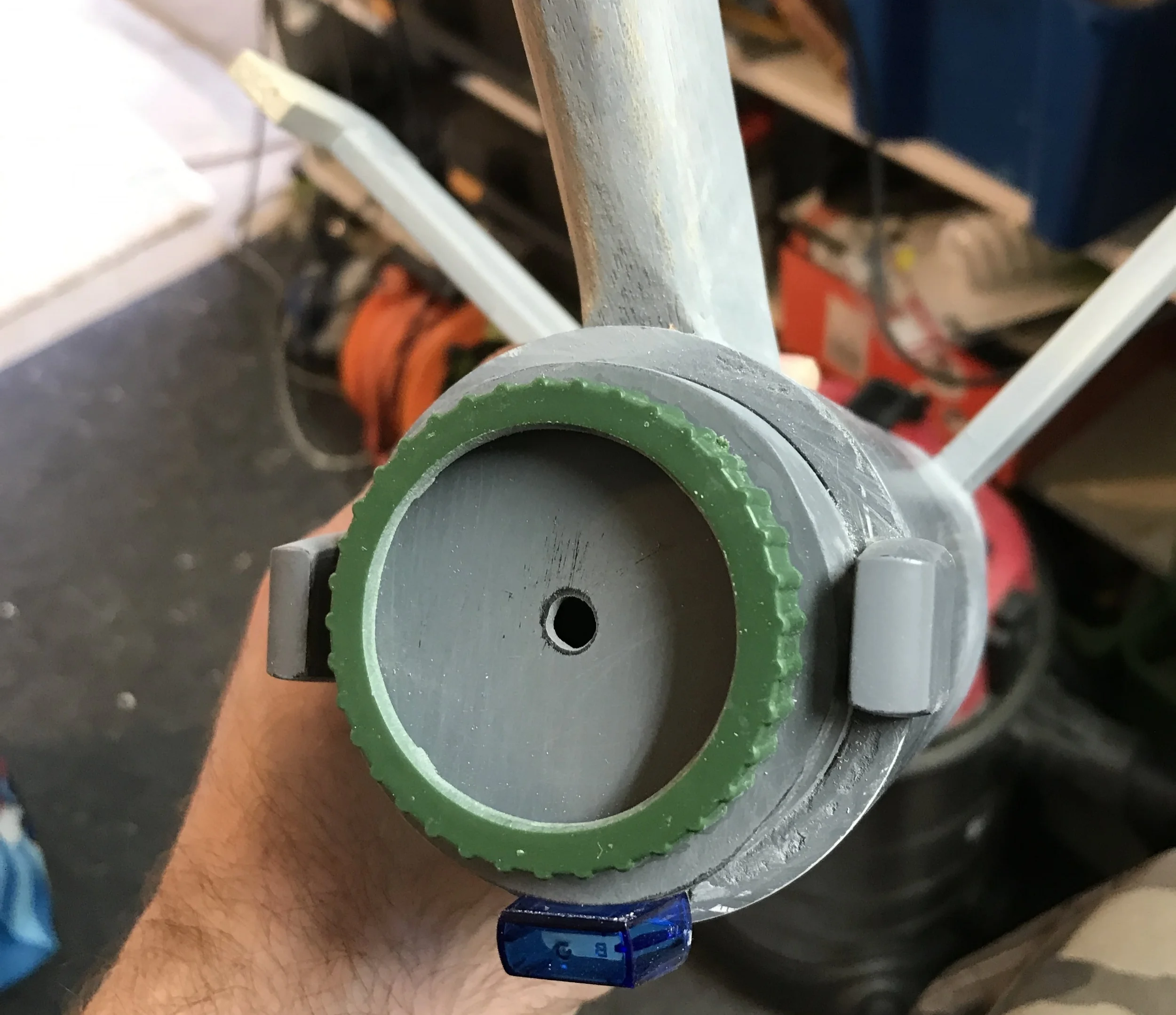
The 50mm PVC vent cowl (cockpit) actually has an external diameter of 60mm, so everything is scaled from that. The bonus to using 60mm to measure from is that all of the round parts on the ship actually marry up to PVC pipe component sizes, so the circular cannon mount thingies in the middle are 100mm pipe caps (120mm ext. diam), and all of the round vent thingies on the rear will be 40mm PVC tube pieces.

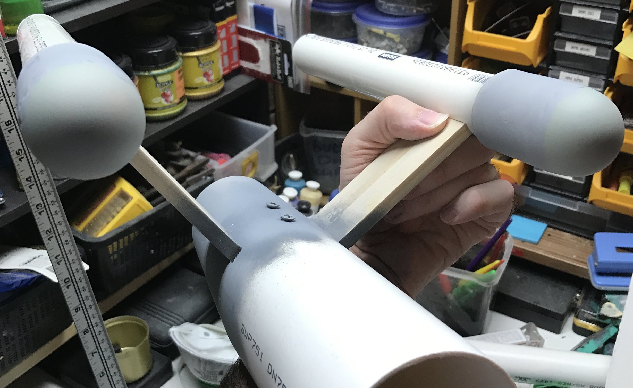
The docking corridors (I'm making these names up as I go along) are getting built up to the right heights. I'm pretty much just "sketching" a shape here, trying to get all of the important parts to be a) fairly solid, and b) the right size.
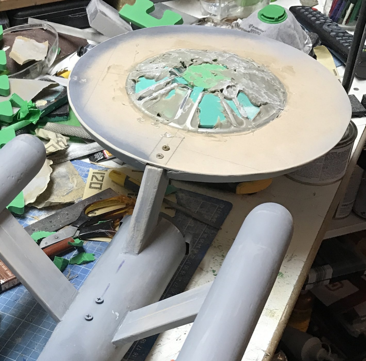
Not entirely sure how I'll approach filling the ribs. Initial plan is expanding foam, then bondo. Failing that, EVA foam, then bondo (tedious to cut all the EVA foam up though, been there done that on the Enterprise saucer), failing that I might just make more ribs and skin the whole area with styrene. Who knows! This is an adventure.
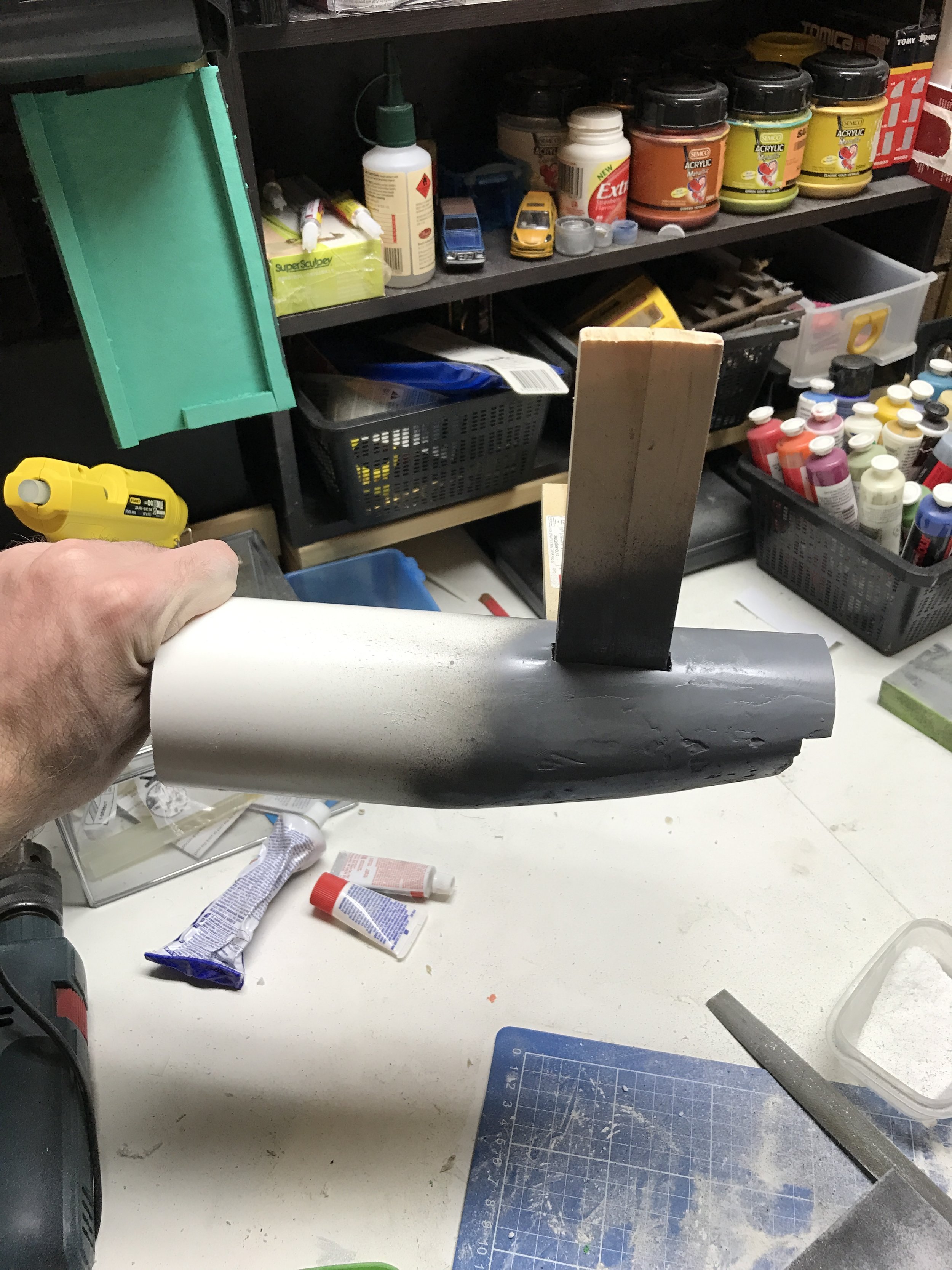
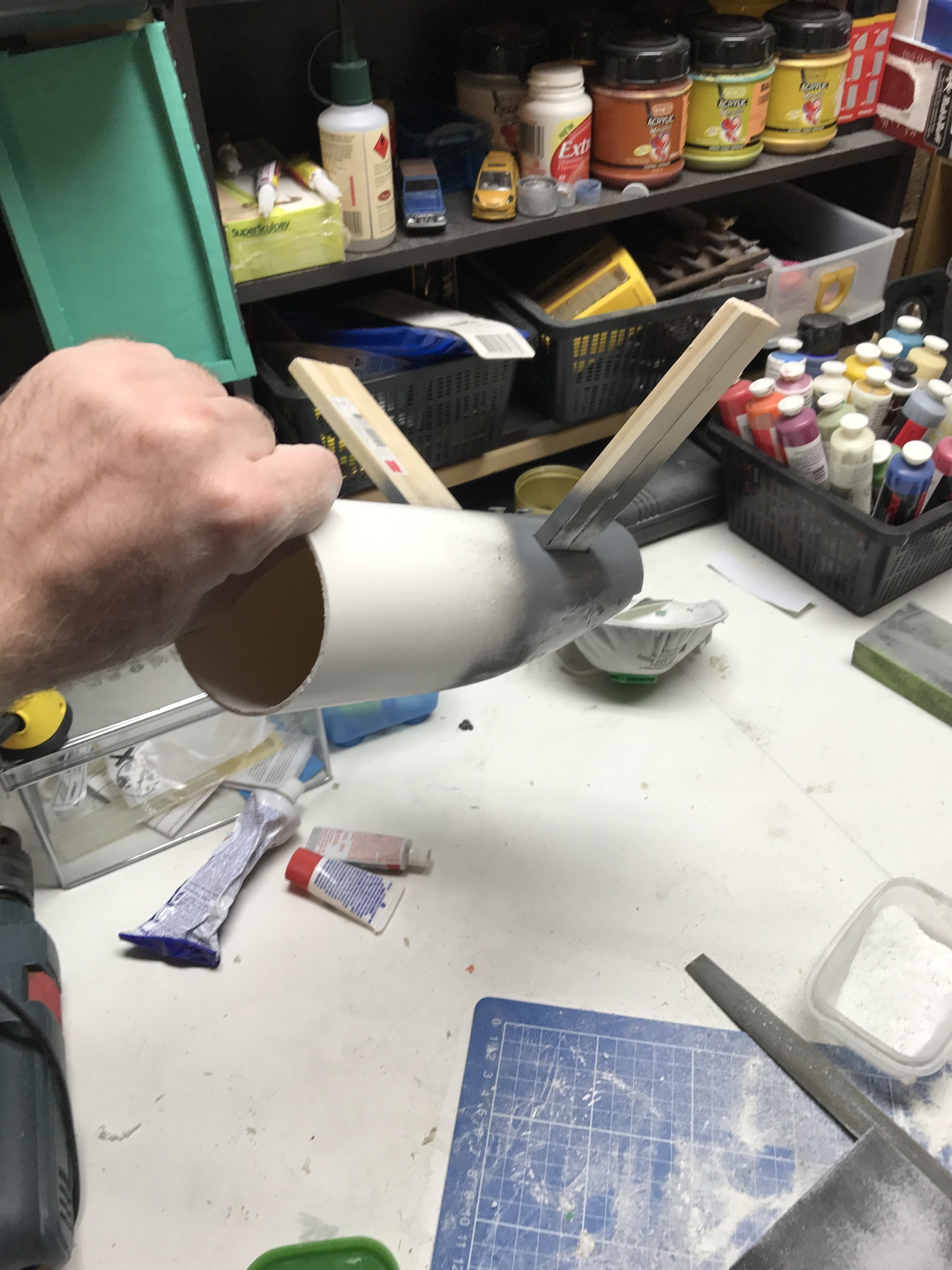
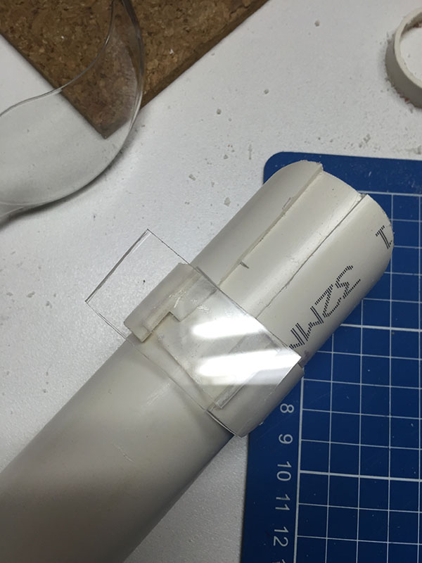
I've added some extra pipe portions to the cockpit corridor. The piece on top appears to give the correct angle, I'm hoping it'll look "right" once the hull plates are snuggled up around it.
The round holes on the mandibles are bigger than they need to be (actually, the mandibles are also thinner than they need to be) because the whole front area is generously undersized to allow the surface to be built up with some layers of...whatever...to get the shapes and textures right.
My plan is to detail the entire exterior using whatever I can find that seems to look right, mostly junk, but we'll see what happens.
The only concession I think I'll make is that I usually don't use a lot of styrene sheet (because it's expensive), but I can't think of any other way to make a tonne of hull plates without losing my sanity entirely, so styrene it will be.
I'm at the point in the build where I start tearing out parts that I've already made because they didn't work so well, or because I came up with a better idea.
I wasn't happy with the "make ribs, fill with something" approach to making the dome shape, because I couldn't shake the feeling that there had to be something I could buy that was just the right shape. So I went hardware store hunting again.
BAM - a garbage bin lid. Obviously it has some issues, though. The centre part is raised. The total diameter of the curved part is not quite wide enough. And it has "60L" on it. Dremeled the heck out of it. Took the lip off, cut the centre piece out and re-insterted it without the offset. So far, so good.


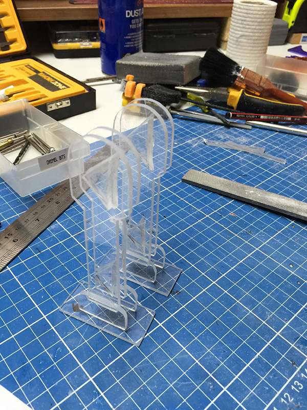
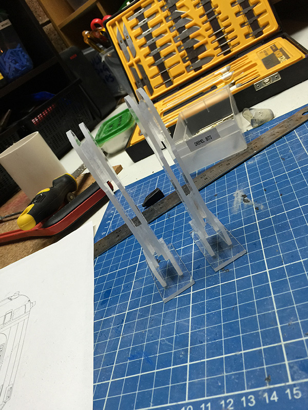
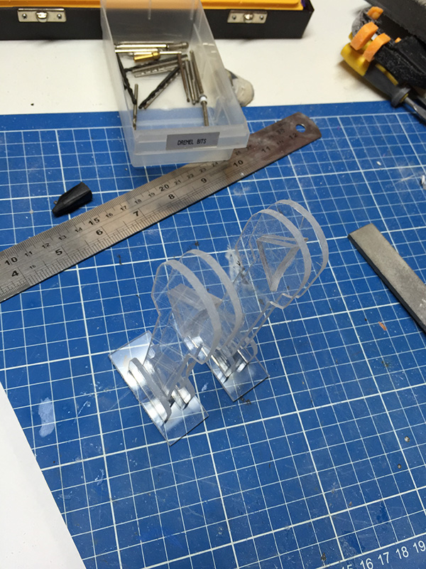
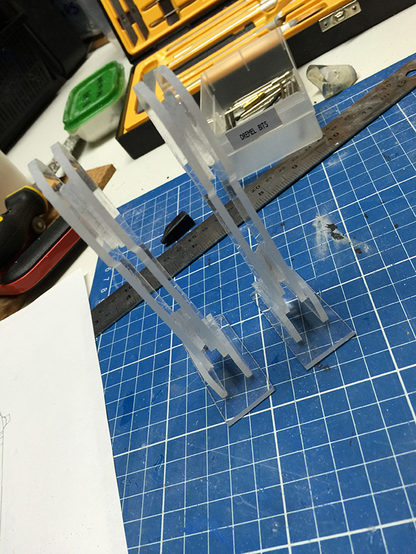
I wish I had access to a laser cutter.....but I don't, so instead, I cut four pieces of tedious acrylic by hand, and messed about with them until they fit right. Also detailed the little round tubs on the mandibles with some USB thumb drive lids, lollipop sticks and cable ties for texture.

It's the 60 litre version of the Falcon.
I'm happy with the shape of the "dome". It's still rough, but it'll be covered with little styrene hull plates, so the texture won't be evident.

Mandible detail cut.

Primer.
We we have an engine deck. It's styrene, warped with a heat gun to the curvature of the bin lid, and raised above the surface on a few stacked strips of styrene. Worked fairly well. It has a few uneven areas due to heat gun brutality, which will require some filler later, but generally speaking, it's working quite nicely.
Dug some holes in the bin lid for the maintenance tubs, which will probably be detailed with chunks of old circuit board and piping from lollipop sticks and whatnot, but let's not get ahead of ourselves...
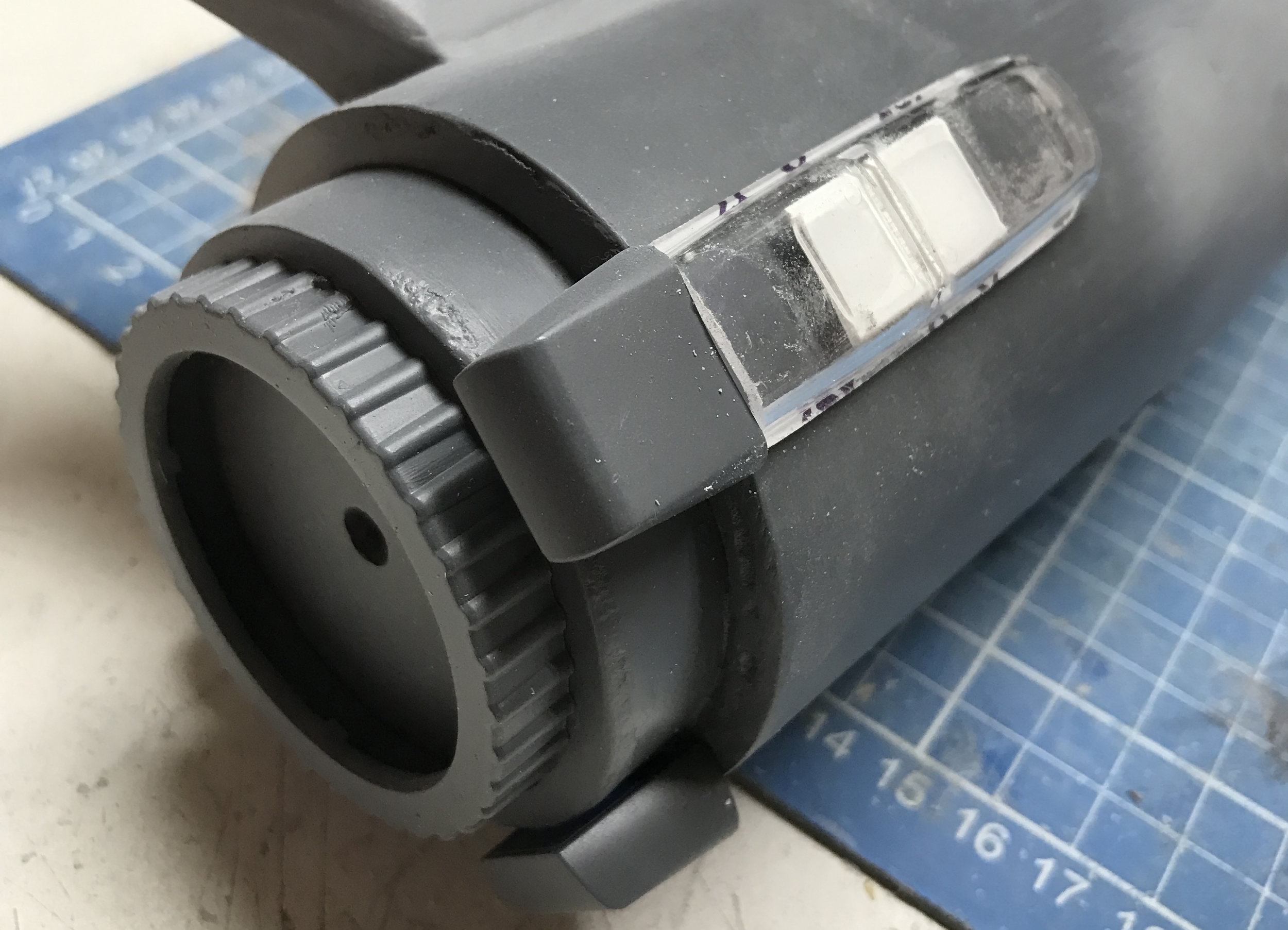
Messed about with the cockpit (plumbing vent) a bit. Filled in the lower "windows", added angled pieces to the upper windows. Still need to add some thin borders to the windows and some kind of glass. Drilled the end of the plumbing vent out, added a disc of styrene for the end windows. Decided to sacrifice one of the upper windows on the end of the cockpit for the sake of practicality, so there are three wedge-shaped windows on top, not four. I'm not losing any sleep over it.

Engine deck and further detail.
The plan is to cut panels to cover the larger areas (each "pie wedge" of the round part, etc), then mark the panel gaps on the whole piece with Sharpie, then cut on the Sharpie lines and file away the visible Sharpie, theoretically leaving a bunch of correctly shaped panels with fairly even gaps between them. At least, that's the plan.
I forgot to cut the little notches into the edges of the panels, but again, I'm not worried, it won't look out of place for the turret to be missing notches. I'll put notches on the main panels. Whoops.
The below photograph is testing a theory -- I'm considering using flattened out binder clips for the engine flaps. It's not accurate, but neither is a garbage bin lid. I think they convey the concept of "engine flaps" quite well.

Binder clip engine vanes.
Paneling the cockpit tube involves putting masking tape on the tube, drawing the panels, peeling the tape off, sticking the tape onto styrene sheet and cutting out the panels. Not as difficult as it initially seemed.
Circuit boards from an old cable modem make great greeblies for inside the maintenance wells.

Cockpit tunnel paneling.

Dish paneling and circuit board greebles.

Top jaw box made from MDF, styrene and miscellaneous greeblies. 100% completely inaccurate, and I actually end up deleting all of the surface detail and rebuilding it later. So, there's a minute of your time completely wasted. You're welcome.

Three exhaust vents completed.

The exhaust vents are made from the lids of these chewing gum containers, with cable tie "ladders" for the vent grilles.

From the sublime to the ridiculous: Texture and greebliness on the inside of the mandibles is provided by some clothes pegs.

Mandible panels.

Panels and pegs and greebs, oh my. These details are made up from cable ties (green and black bits), clothes pegs (red/green), parts from broken printers, cameras, clocks, some completely unidentifiable bits and pieces, USB lids, "lollipop sticks" from a craft shop, plastic bits from inside Nerf guns, circuit boards and no doubt many other things.

Primer makes it look a million bucks.

Airlocks. Not 100% happy with them, because they're hideously inaccurate and look kind of awful. (They look better with primer, but I didn't take a photo.) I might re-build them, depending on how much they annoy me. Still need to make some kind of conical bevel on the edges, I'll try to get that part right, at least.

A shot outdoors to reveal all of the detail and all of my mistakes!

Edge greeblies. Consists mostly of random unidentifiable plastic and metal junk. I spent some time wandering around the local garbage dump's "reuse store" collecting everything that looked tiny and interesting, so I have no clue what any of it is. The long green things are cable ties, the other green things are clothes pegs (surprisingly detailed on the posterior side, easily cut up, very handy). The aluminium things I believe are hardware for door or window rails, but I'm not 100% sure. The blue thing is an electrical cable joiner. Also a toy car wheel, and a few pieces of chopped up Hot Wheels chassis.

Newly rebuilt jaw box with much cable tie detail and solder piping. The surface has some awful texture from where I've torn the original greeblies off the MDF sheet...but it all adds character, I think.

Aaaaaand I've also torn down the engine deck and basically started over. Among other things, I found a bunch of tyre valve inserts (left of photo) at the local junk shop. Big ones and small ones. I used the smaller sized ones between the engine flaps, for now. I'd have preferred them centred on the flap, but I'm lazy and couldn't be bothered dremeling out a little channel in each of the steel bulldog clips/flaps. If I have to wait longer than I expect for my styrene sheet to arrive, I might still do that.
I also found some old electrical clips (the very deteriorated looking white and blue things) that seem like a reasonable approximation of a couple of kitbashed parts.
And I built the little panels that go behind the main vents using styrene, cable ties (of course!) and washers. I think they're a pretty decent facsimile of the "actual" parts. They'll look better when there are some pipes and whatnot going over them.

It's a dish! It's a dish made from the bottom of a plastic champagne glass (much like the dish on the Enterprise) and some of my favourite cable ties. Again, they seem to replicate the appropriate parts within a reasonable tolerance of accuracy. (One can only expect so much accuracy when one's satellite dish is a wine glass.)

Support structure for the wine glass -- legs and arms cut from acrylic, a felt tip pen lid (red) and an antique cable clamp.

Added window frames to the cockpit.

Some semi-accurate detail on the top of the docking corridor. The green and white bits are reasonably somewhat kind of sort of what they're supposed to be. The brass thing is actually an earring -- found two of them (earrings often come in pairs, who knew?) and thought they'd make some nice greebs. The round gizmo is a large washer with some cable ties (of course) behind.

That, my friends, is a quad laser cannon. It's a quad laser cannon made from junk, but regardless, it's a quad laser cannon. Styrene, lollipop sticks, tile spacing wedges, a USB flash drive lid, a gear and some plastic goodies from an old SLR camera, washers and of course.......some zip tie bits and bobs.

And now...............paint.
The plan, such as it is, is to paint the maintenance hatches and the entire equatorial greebly section matte black. The main reason I'm doing it this way is that this thing is made from so many different materials that I can't be super confident that the glue on the greebs will hold together once I try to cram black paint and black wash and dry brushing and weathering powder and who-knows-what else in there. So...starting with black makes that a WHOLE lot easier.
(Besides, it looks awfully sexy with the equatorial 'trench' painted black. Who knew?)

Base colour -- Rustoleum "Heirloom White".

Masking for the red parts of the ship.

We have red! The colour is "Hot Lips", with a random overspraying of metallic red as well, just for...variation. And because shiny is awesome.

Medium and medium-dark grey panels. First colour is "Windspray", which is actually a Colorbond fencing colour. I was delighted to find the can at the back of my spray paint shelf, as I didn't think I actually had four shades of grey to achieve the "correct" effect on the panels. Second colour is "Ito". Aren't you glad I'm telling you all of this?

Dark grey. Colour is called "Namadji", and verges on brown. I'm really happy that the "Windspray" is kind of a cool grey and "Namadji" is a warm grey. Gives it some variation and interest.
I've taken the masking off the maintenance wells, so this is about as "pristine" as the Falcon will ever be.

First, the exhaust vents need to be BLAAAACK. Masking took ages, but was worth it -- as masking often is.

Exhaust vents painted.

And there's our initial black wash. Now, it won't surprise you to know that I'm doing all of this 'wrong', and I'm not using expensive oils for my washes. All of the weathering is going to be done using acrylic paints (the kind that comes in tubes for a couple of bucks, school paint), some sidewalk chalk and the most outrageously expensive part of the whole weathering process will be a pack of artist's pastels. So...this should be interesting.
The first point of failure (sort of) has been the initial black wash. I forgot to include soap in the recipe, so there were some spectacular issues with surface tension and my wash retracting away from some of the greebs/edges/features. Oh well. We live and learn.


Panel detail. Weathered inside with artist's pastel and acrylic paint and water and whatever other stuff I could find to grunge it up in there.

And that, as they say, is that.

I ended up installing a row of LED Christmas lights into the rear, behind a strip of transparent USB thumb drive lids.
So that's how I made that. And now it sits in my garage and collects dust, alongside the Enterprise.
Space. The final frontier. These are the voyages of...some junk from the hardware store.
After making R2D2 from hardware store materials, I thought 'hey, why not build the Enterprise the same way'. So, uh, I did.
Or, more to the point, I stuck three pieces of PVC pipe together on a crude framework of wood joined together at 45-degree angles, and left it on the workbench for six months.
As you can see from the above photograph, it's clearly perfect and requires little more than some paint and decals.
Maybe not.
It sat like that, with duct tape and screws, for a long time. It was thrown about, shoved aside and piled beneath other things. Eventually, I decided to do something with it.
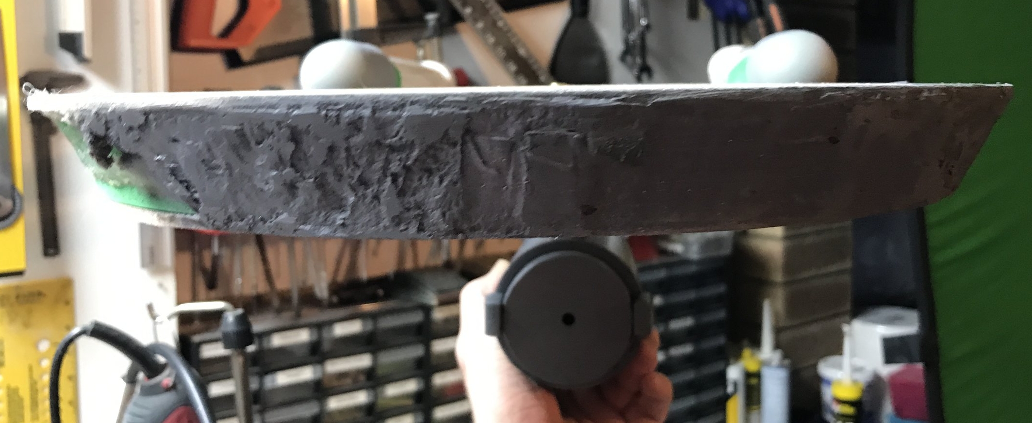
The biggest challenge, believe it or not, was to figure out a way to taper the engineering hull into shape. I had considered just cutting the bottom off the PVC pipe at an angle and being done with it, but I also cut a series of slits into the pipe and pressed it in around spraypaint can lids of various sizes (as pictured very ineffectually to the right, also coated in a carcinogenic amount of Bondo). I wasn't working very seriously on the project at this point, so I didn't take too many photos. I was sick of the thing hanging around, so this was a fairly brutal attempt at either solving the engineering-hull-taper-problem, or ruining it so I could throw it the hell away.
Ultimately, it worked.
Below are a bunch of photos of the bottom of the engineering hull once it had been roughly hewn into shape using a rasp and files, and squirted with a coat of primer to allow the shape to be better identified. I eventually took a futher "scoop" shape from the very end, beneath the shuttle bay, to give it a more accurate (but not perfect) shape. It's good enough. It's plumbing parts. I'm okay with this.
Here's the engineering hull with the nacelles attached:

Next up, I tried to somewhat shape the shuttle bay, and made some rounded caps for the front of the engine nacelles.

Okay. The shuttle bay now has a shape for its little "roof" piece, which was rounded off on the ends using files. I added a couple of extra millimetres of thickness to the "roof" part with some styrene sheet offcuts, to give it a bit more rigidity and the illusion of sturdiness.
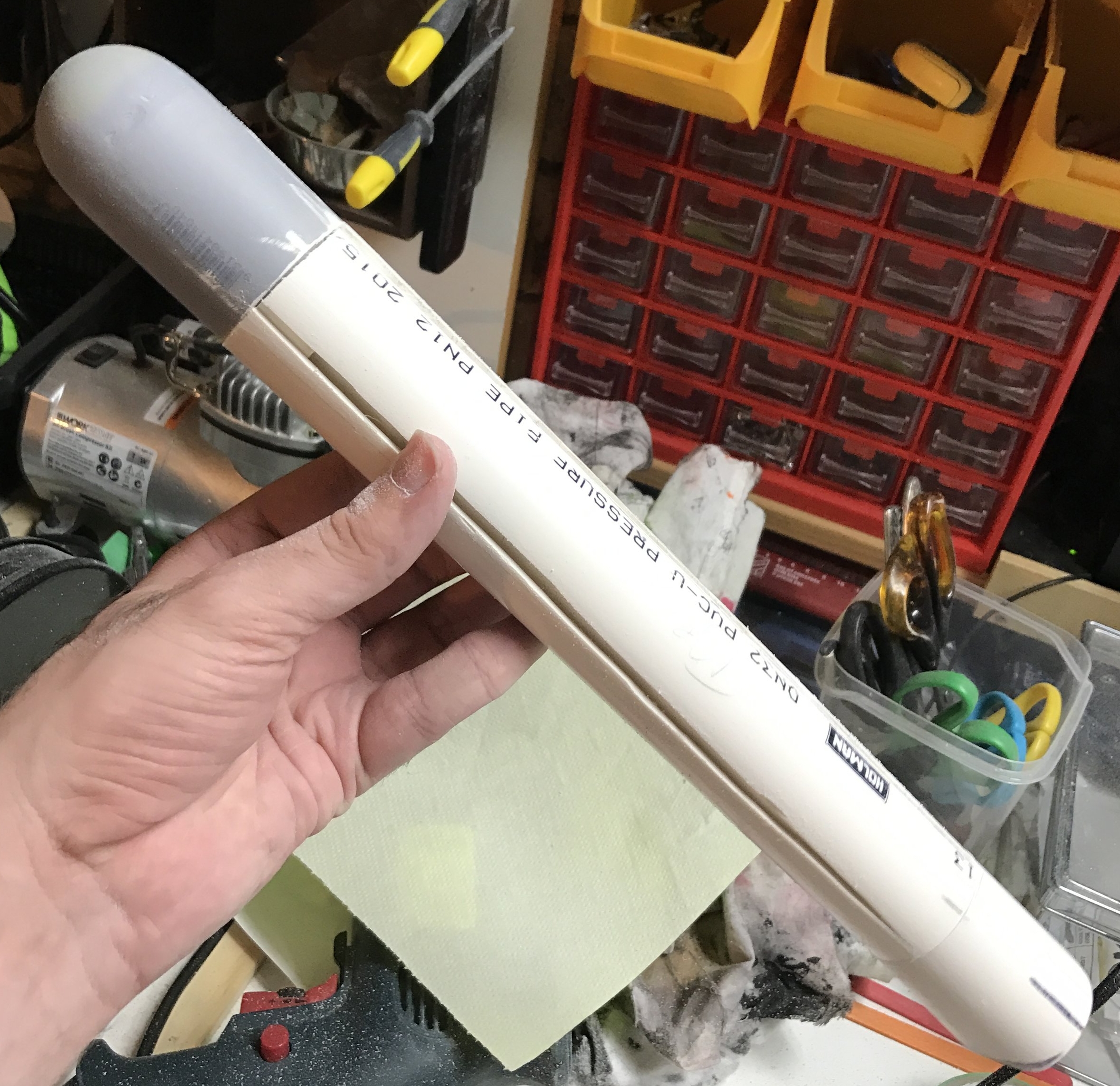
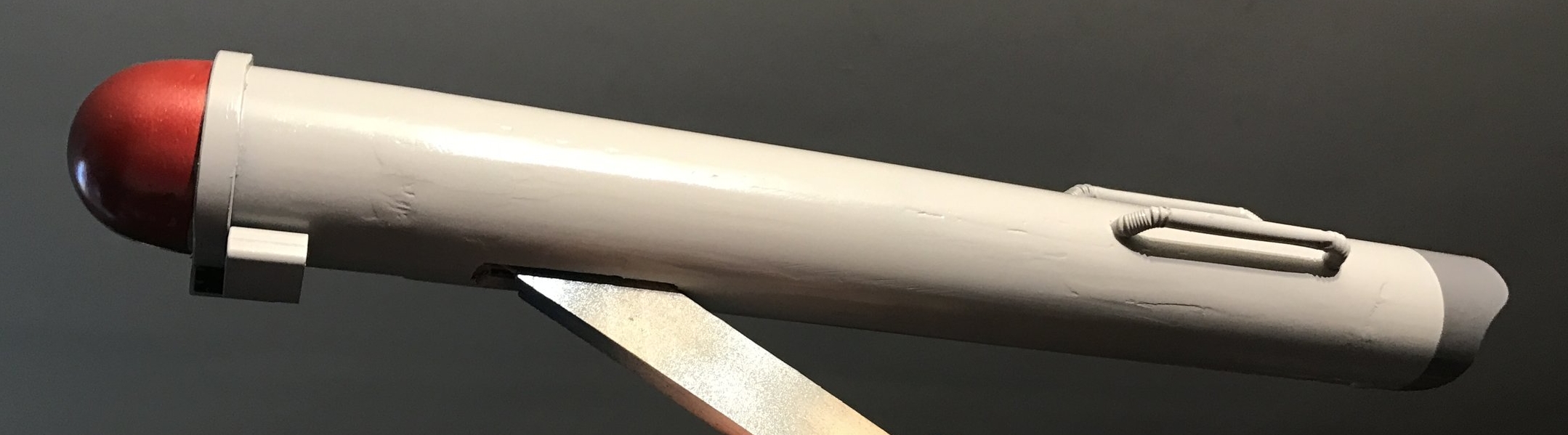
The nacelle end caps (aka "the red bits", or "the domey things") are made relatively simply. The nacelle tubes are 37mm PVC pipe. I cut pieces of 40mm PVC pipe to slide over them (quite loosely, I might add), and glued ping ping pong balls to the ends. As luck would have it, the diameter of a standard ping pong ball is 40mm, so with copious amounts of highly toxic filler shoved in the gap, they blend seamlessly into the tube.
Allow me to address something obvious: They look ridiculous. The reason for this is that I had hoped they would not look ridiculous, and my hope failed me. When these kinds of problems arise while I'm building something, I find the best approach is to ignore them, and trust that a solution will pop out of the ether later on. Spoiler: It does.

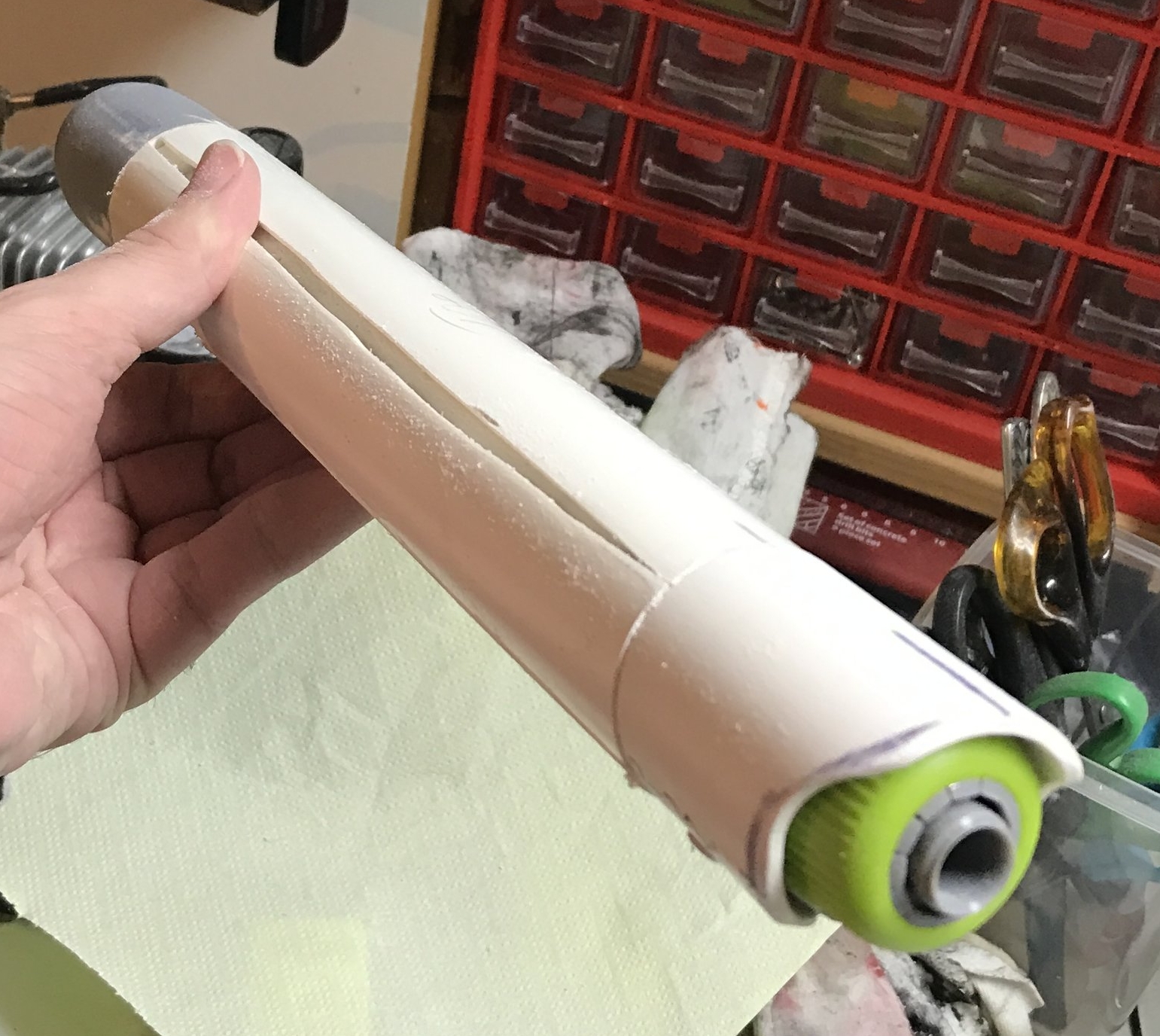
Enterprise design purists may wish to look the other way for a moment: the ends of the nacelles are going to be made from hose fittings. Wait -- let me clarify that: The ends of the nacelles are going to be hose fittings.
I'm okay with this. This thing is made from hardware store parts, mostly from the plumbing aisle. It seems only fitting that the engines should be garden hose connectors.
Thanks to The Reject Shop, I managed to find two garden hose connectors and a set of LED string lights disguised as miniature light bulbs (centre of above photograph), one of which was sliced and diced to form the spherical door of the shuttlebay, which needed a little styrene platform under it and a generous coat of primer. (This part fell off many times between now and the final product, but I'll spare you the anguish.)
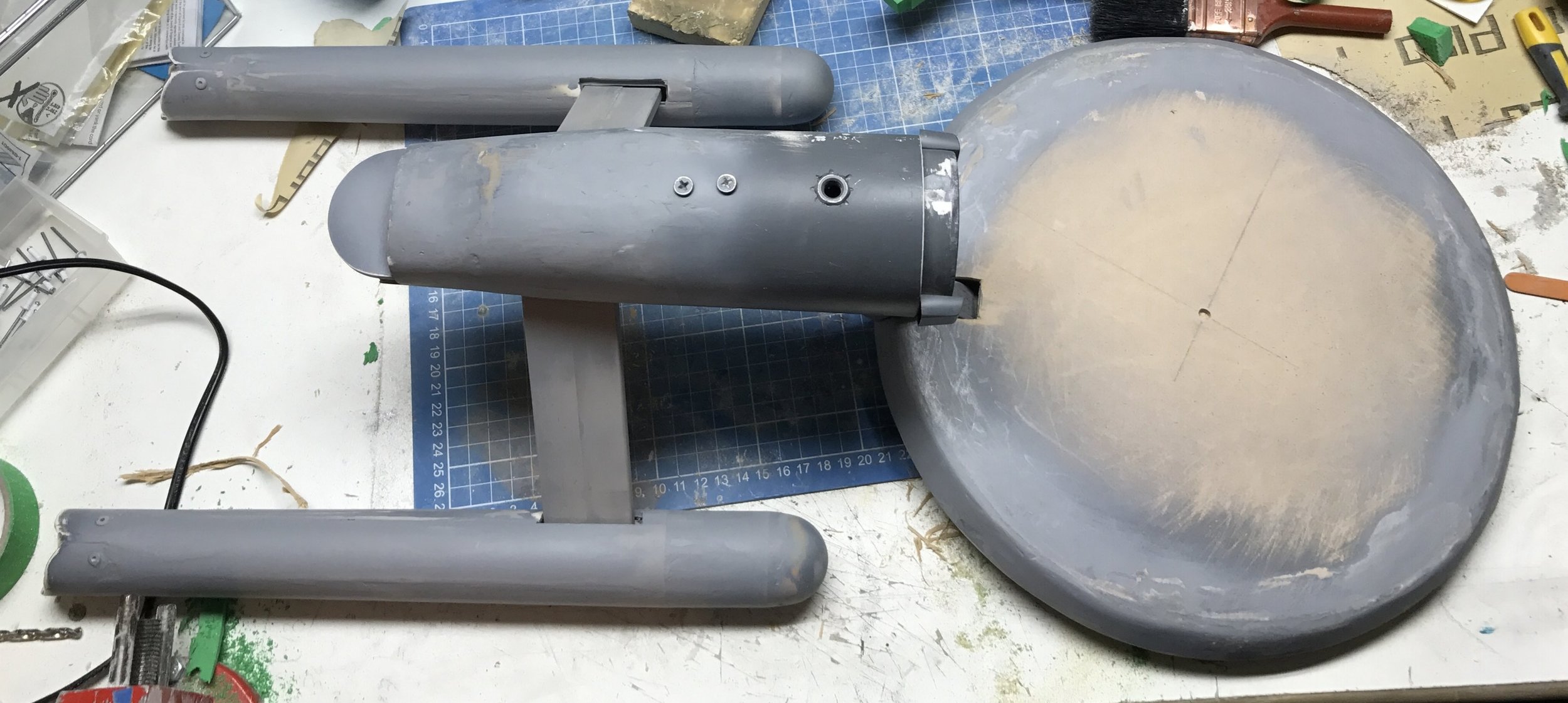
Now, as you can probably see, it's starting to look a bit more like a starship. We still have ugly nacelle caps, but I have gone to the trouble of making some nice little PVC covers for the rear of the engines, which I'm very happy with. I had to use some scale-inaccurate pop rivets to hold the covers on, but I'm okay with that. These things happen.
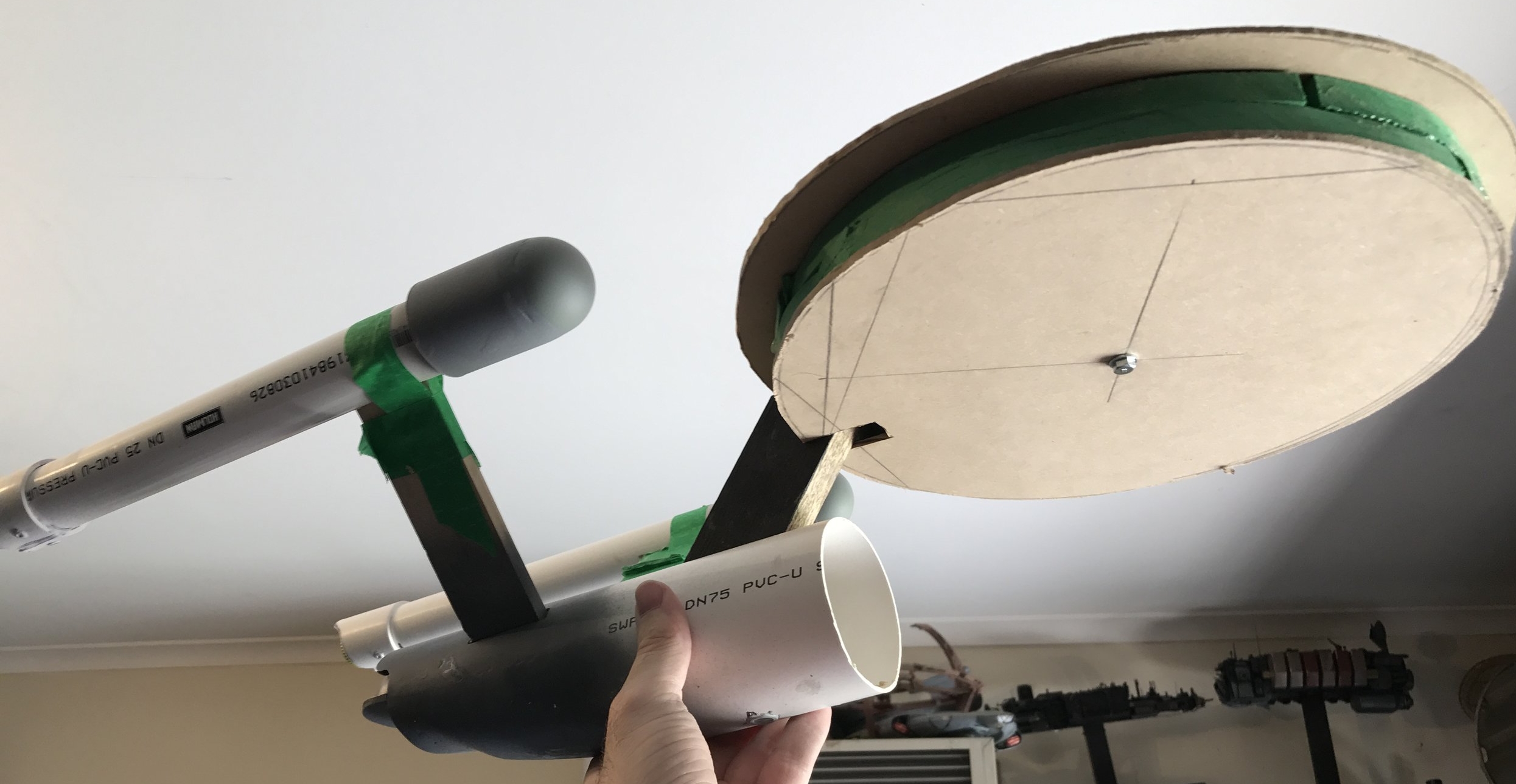
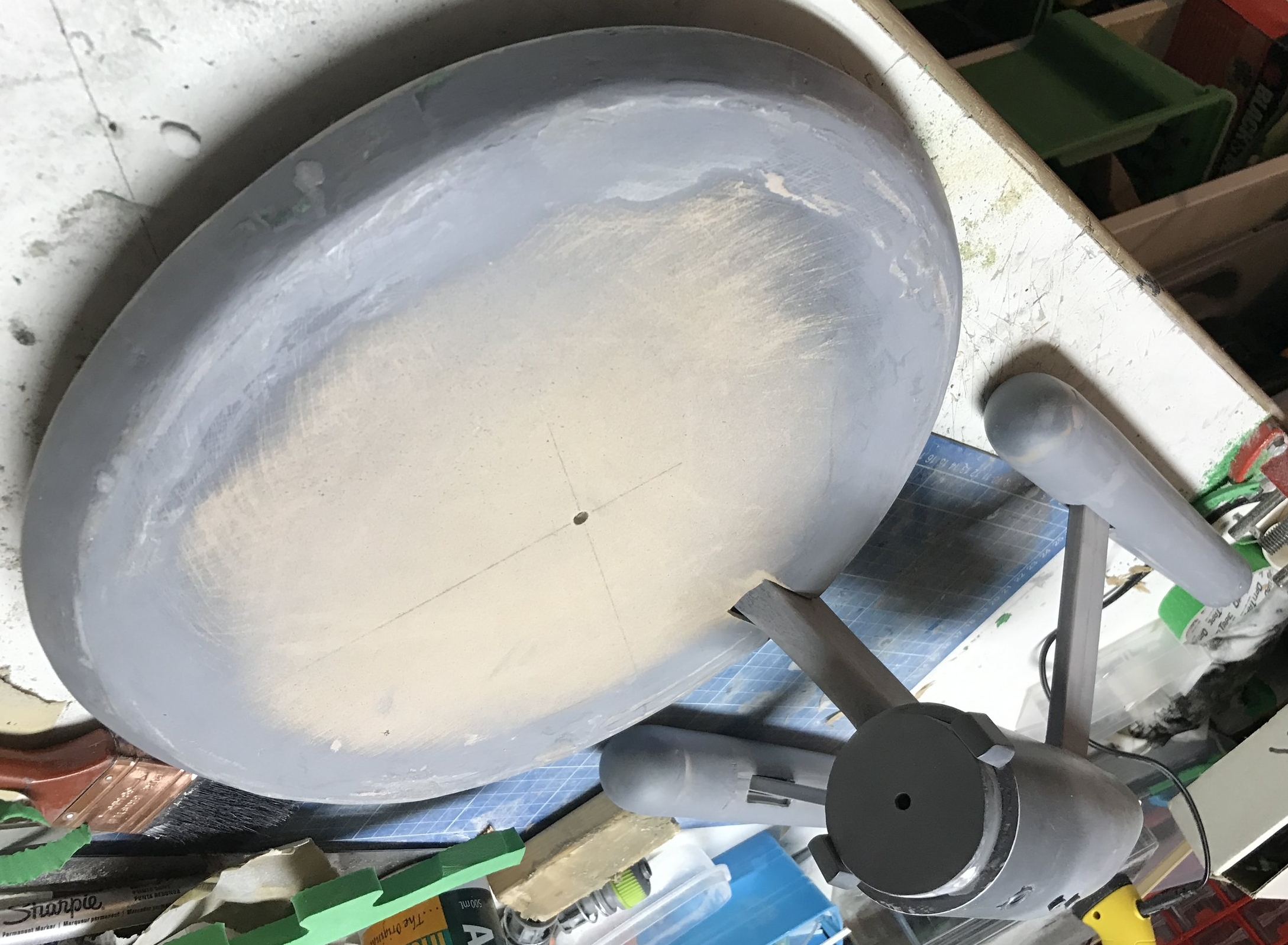
The saucer is now...present. I had many ideas on how to approach the saucer, from dinner plates to acrylic plastic, to making ribs and skinning them with something. Ultimately, I settled on two discs of thin MDF propped apart with a ring of EVA foam. Here, you can see I've used two sheets of EVA foam floor mat, but I eventually reduce it to one, as two is clearly far too thick.
No work so far on the deflector dish, it remains a gaping hole.
You can see the mounting nut embedded in the very bottom of the ship, though. It's held in with Liquid Nails and a copious shell of bondo on the inside. Hopefully, this nut will a) hold the weight of the ship, and b) be roughly located at its centre of gravity. Difficult to tell the latter, as I have no idea at this point what the thing will end up being made of, and whether it'll be front or back heavy.
One more thing to address, here: the neck. It's a bit of wood. It's supposed to be at a 45-degree angle, but I had to make it 35-degrees to accommodate the asteroid-sized hunk of bondo inside the engineering tube that holds the engine struts and mounting nut in place. All things considered, it still looks appropriately angled. If you approach my Enterprise with a protractor, you'll be severely disappointed.
Here's a lovely front view, showing how stupidly and ridiculously thick the saucer is. It's already loaded with bondo, and is starting to take shape. To fix the thickness issue, I ran around the equator of the saucer with a rotary tool, tore the EVA foam spacer in half, and glued the bottom back on. Some times you just have to be brutal with these kinds of projects, and fix the fine details later. I've learned this is a really important rule to follow -- just fix it, otherwise you'll dwell on it and sweat over it, and it'll never be fixed at all.
Okay, time for a solution to the ugly nacelle problem. I wanted to make the nacelles taper gently from front to back. The idea with this project was to nail all of the big elements of geometry about the Enterprise, and the tiny details -- hopefully -- would fall into place. Tapering the engines was essential. My initial plan was to cake them in Bondo and sand them until appropriately tapered. However, that plan would have involved a billion dollars worth of Bondo (the stuff is not cheap), and would have taken several decades off my life (the stuff is not safe).
Instead, I found a more elegant solution. I took a length of the outer-diameter PVC pipe and sliced it into quarters, then used the four quartered panels to taper the engine from front to back. A bit of Bondo in the gaps, and we have an engine. Or two.
I had no plan for how to create the raised section of the saucer. Instead, I went rummaging around in the various boxes of junk I keep in the hopes of one day solving problems like this. I found a speaker grille from a cheap car stereo, which quite nicely replicates the shape of the saucer hump.
After insetting the speaker grille into the top of the saucer, I packed the holes in it with EVA foam off-cuts to prevent filler wastage, and started filling the surface with Bondo. It took quite a bit. It was not particularly fun. It worked out okay in the end, though.
An upside-down photo of the Enterprise on the workbench. The deflector dish location has now been somewhat fixed up -- a piece of PVC pipe, some acrylic sheet, a couple of plastic lids from USB thumb drives. The underside of the saucer remains undetailed, I have not found a solution at this point to create the hump on the bottom.
Here's the underside of the ship at this point. Not much to see here, apart from the mounting nut, two screws that I have no intention of trying to hide (they hold the bottom of the neck in place) and some obvious issues with the angle of the deflector area and the saucer mounting point.

Speaking of the deflector dish...here's my elegant solution for that. That yellow thing is the bottom of a plastic champagne glass. It's a tiny bit big, but this whole project is a tiny bit inaccurate, so I'm not losing any sleep over it. I am slightly concerned about that very obvious angle discrepancy, the front of the engineering hull doesn't exactly appear flat. Oh, well. We'll press on.

While we're in the party supplies section of the department store, we'd better grab some bendy straws. While not the most robust items to make starship parts from, I got this idea from the insanely incredible work of The Nylon Gag on the RPF, who used bendy straws as part of the detail on his scratchbuilt delivery ship, which means they're totally legal building materials. You can find his use of them here, but do go back to the beginning of the build thread, and do dedicate an entire afternoon to it because you won't stop looking at it. The thing is an absolute work of art.
So, the "handles" on the nacelles are bendy straws, tucked into each other, and homed in little holes in the engines. Incidentally, straws are 5mm across. If you were wondering. I was.
Here's some more detail on the deflector dish mounting area. The green thing is the wheel of a toy cannon from one of those bags of plastic army toys. I stripped the spokes from the wheel, and the textured outer edge seemed appropriate for the deflector region. You can also see another USB thumb drive lid at the bottom, which has not been primered yet,
More deflector area detail, now with primer and a post-it note flag dispenser attached. This thing is wildly inaccurate. Don't judge me.
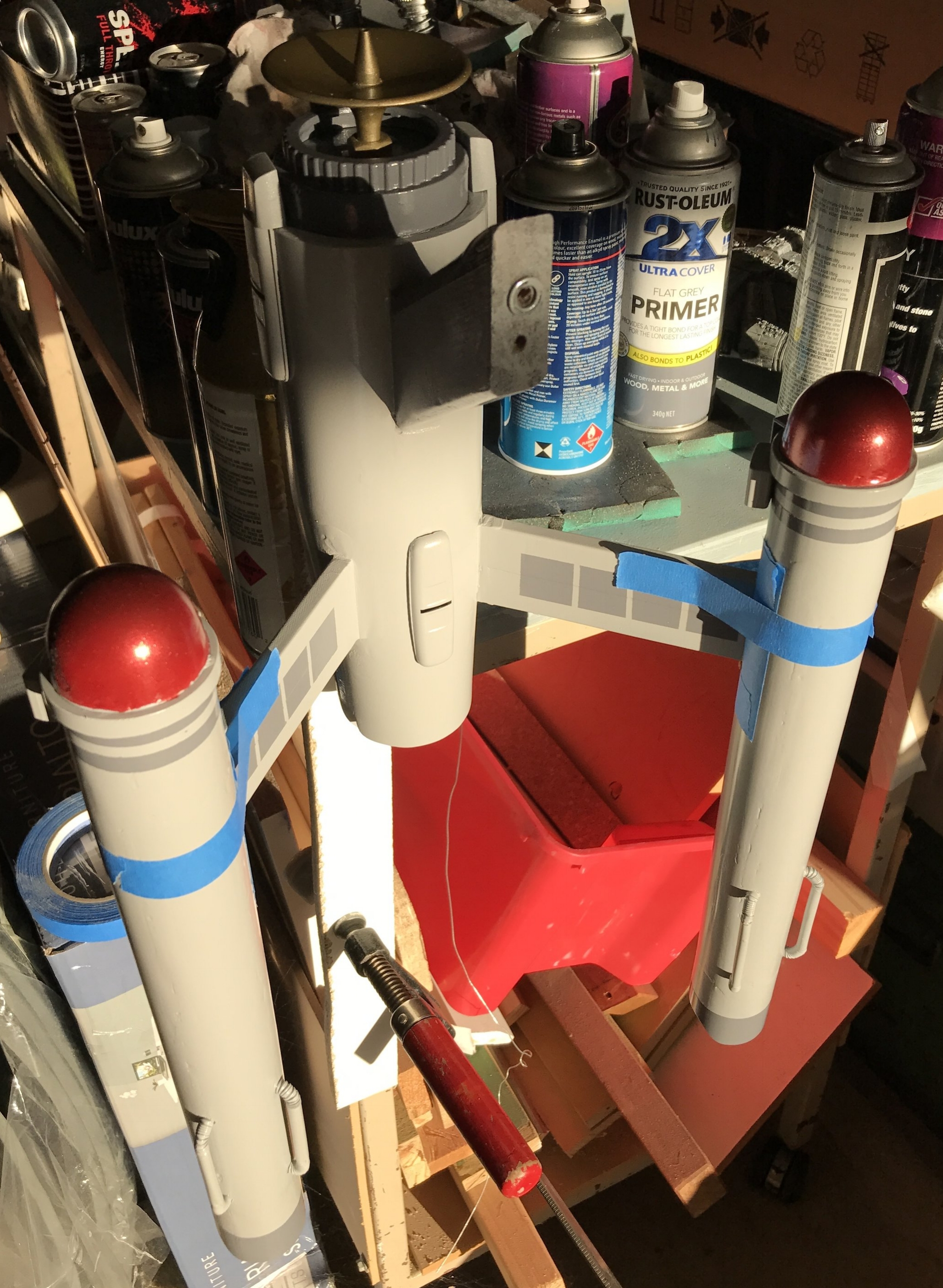
PAINT. We have paint. The body, engines, saucer, etc, will all be a light grey, some details (like the back end of the engine above) will be a dark grey, and there will be scatterings of silver, gold, and obviously -- metallic red. Dulux make some splendid spray paints, in their Duramax range, which dry within about 15 minutes, and can be handled, masked and recoated within an hour. Very cool.
You can't quite tell in the above photo, but the nacelle tips are metallic red. It's very effective.

Engineering hull, now with pale grey paint. I've had to attach the little reversed bracket pieces to the tops of the nacelle stuts, as I'd made the struts a tiny bit too short for the engines to "see" over the saucer, and I needed the little right angle to offer some security to the tubes once they're mounted on the struts. Those little pieces of wood successfully killed both of those birds with one stone. Made of wood. Not stone. That was a terrible metaphor. Also, there were two of them.
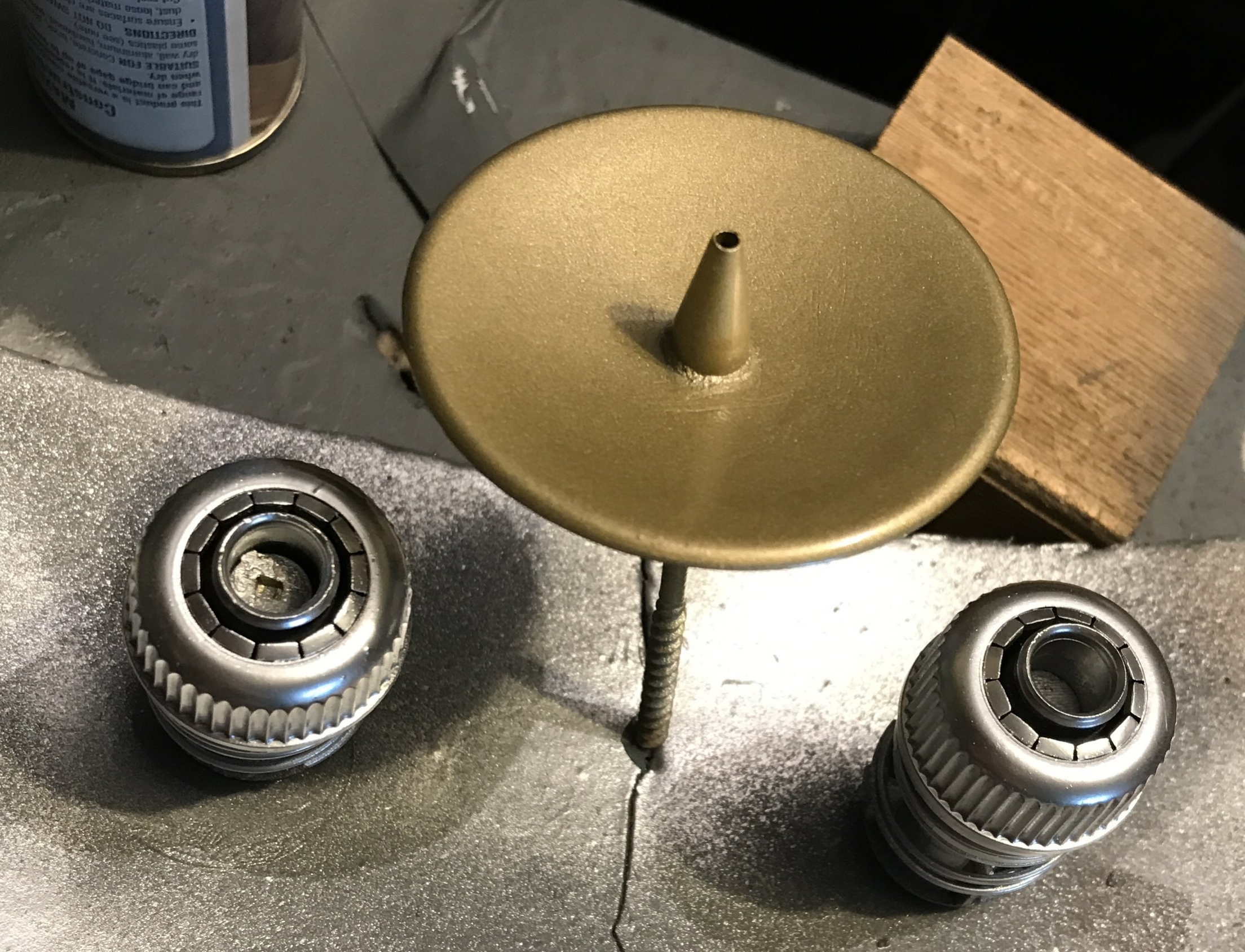
Here we have the nacelle thruster nozzles (or hose connectors, if you're so inclined), and the deflector dish. The nozzles are Krylon classic chrome, and the dish is Rustoleum gold. Just gold. Not metallic gold. Not quality gold. Crappy gold. It should really be copper or bronze, but the only can of copper paint I have is a) hammered finish, and b) clogged like a clogged thing. Hammered finish I could deal with, but unfortunately it's one of the Rustoleum cans with the trigger nozzle thing on top, which is not removable and can't be unclogged. So, long story short, the dish is gold. And I'm okay with that.

Masking, masking, masking. Always buy the blue tape. Spend the money. Buy the good stuff. I like to use the blue tape for any places where the tape comes in contact with existing paint, then I buy a whole bunch of cheap crappy white masking tape to use to hold all of the paper sheets and whatnot over the rest of the job. Don't use the blue stuff if you don't have to, but ALWAYS use it on paintwork.
The point of the above exercise is to create the dark square pattern inside the engine struts, and darken the front of the neck piece and the mounting area for the deflector dish.

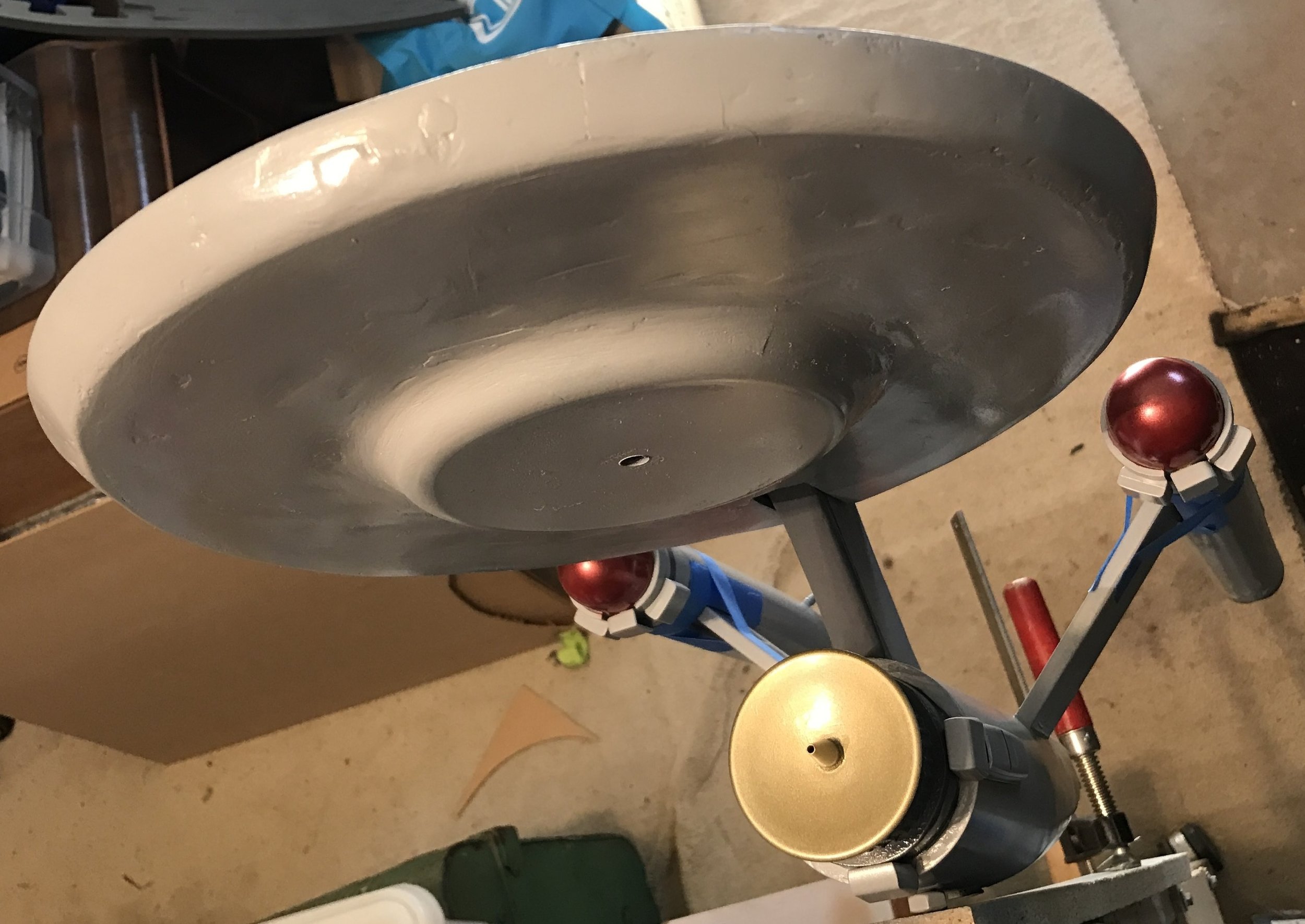
Now THAT's a saucer. It's still looking pretty ugly, but it's a saucer. The surface has now been somewhat adequately filled with Bondo and various other filling methods. The bridge dome has been constructed. The dome is one of those LED string lights shaped like a light bulb (refer above, somewhere around the shuttle bay area), which is set inside the frame of an LED tap light (the round thing), with the pointy end of the "teardrop" shape made from one corner of the plastic box Apple distributes its headphones in. (Or used to, they appear to be packaged in more environmentally friendly cardboard, these days.)

The saucer is starting to look very much like a 1950s alien invasion, and should possibly have its own theme music, played exclusively on a theremin. I cheaped out on the bottom of the saucer, and scrounged thrift stores for an approximately accurate plastic dish, shaved the edge off it, mounted it and filled the gap with a generous scraping of Bondo.
Here, we have a terrible photo of the Enterprise, and an excellent photo of the mess I work in. Don't judge me. I've mounted the ship vertically (using the mounting nut, which appears to be a success), so I can "hang" the nacelles in a fashion that puts minimal stress on the right-angle joint while the glue in the joint sets. I've loaded the little L-shaped mounting pieces on the ends of the nacelle struts with a copious amount of Liquid Nails, masked around the hole on the engines, then mounted them in place and taped them down as hard as possible. Looking at the ship from a distance seems to prove that the engines are level to each other. My biggest fear in this entire project is having all of the parts relatively level to each other, considering the Enterprise, as a design, is basically three things sticking out of another thing.
You can also see that I've added two dark grey stripes to the front end of the nacelles. Because I felt like they needed two dark grey stripes.
This might be the first relatively complete photo of the ship in it's "normal" orientation, even though it's still hanging vertically.
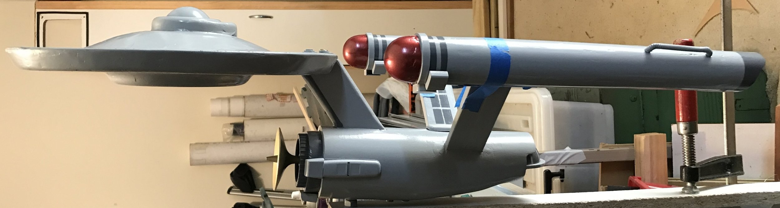
And side-on, demonstrating that -- against all odds -- everything seems to be relatively level. Awesome.

Human for scale. The ship is 70cm long. It's not small.
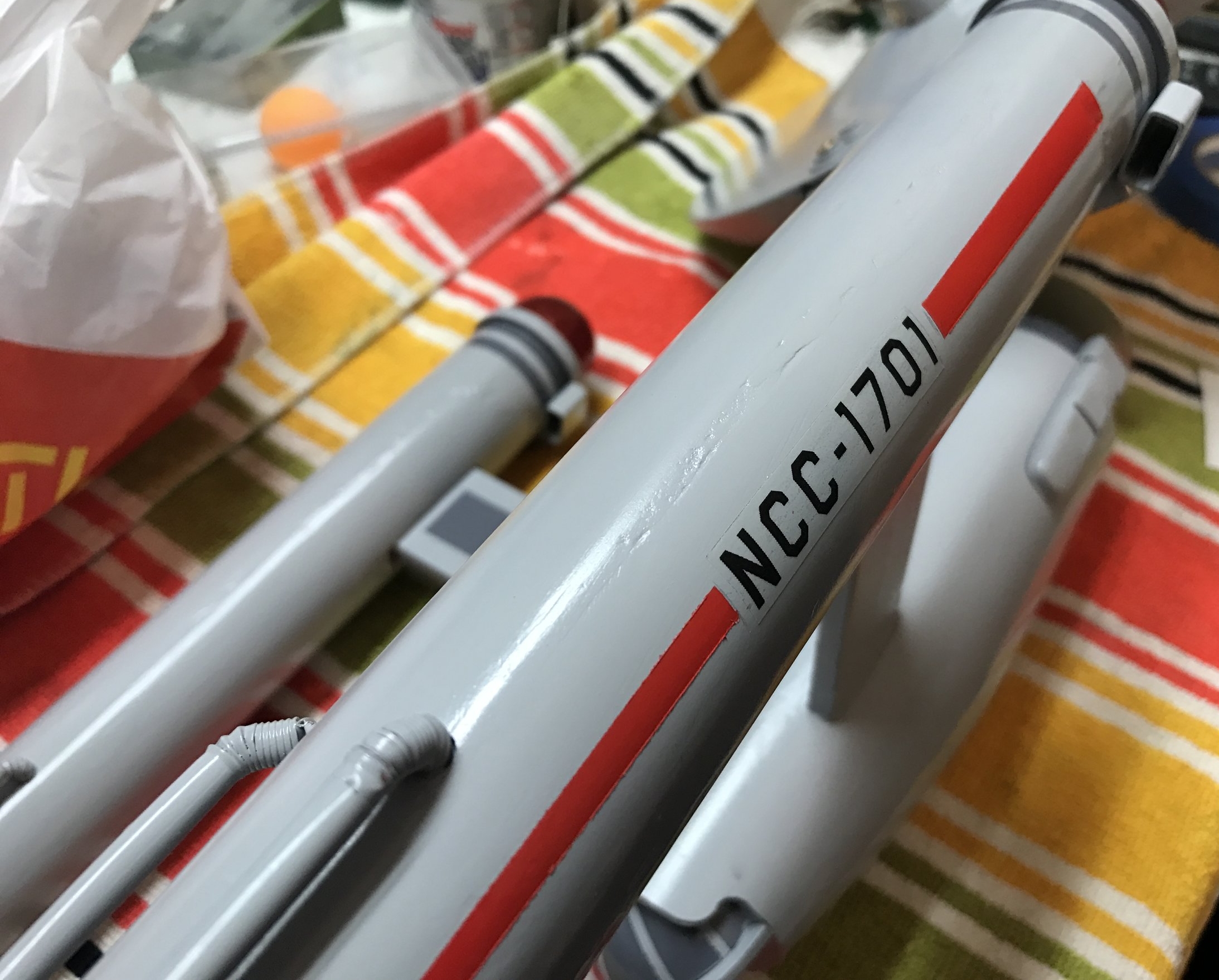
The red markings were masked out (using blue tape, of course), then sprayed with Dulux Duramax "hot lips red" paint. The registry numbers are laser-printed onto clear Avery printer labels, which -- at this point in time -- appears to have been an effective solution. I have a feeling the labels will yellow over time, but we'll see what happens. It's no big deal if I have to re-finish this thing at some point in the future.
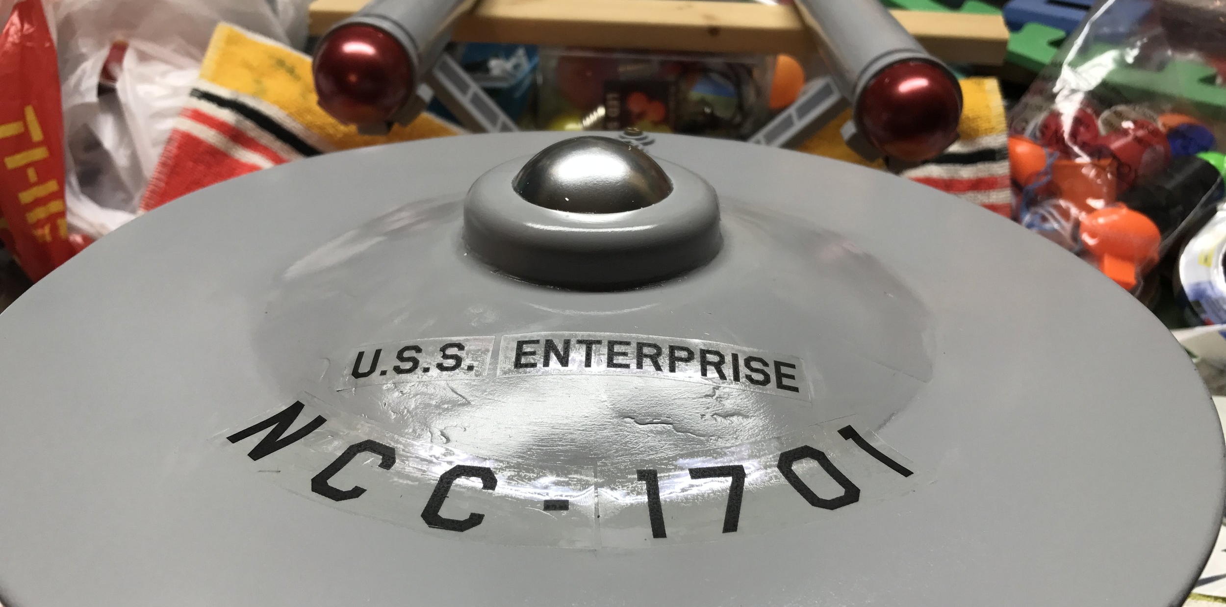
The bridge dome is now chrome silver, and we have hull markings. The stickers seem reasonably resilient to curved surfaces, but again, that's something that will be discovered over time.

And THAT is a finished starship. Final touches include an impulse engine (wildly inaccurate, but it's designed to cover screws, so...it'll do just fine, thank you), painted details on the saucer and running lights (pearlescent pin heads).

And one final photo, sausage dog for scale. The gold squares on the saucer should actually be white, but I had no white paint handy, and I didn't want to use chrome again. I'm happy with the gold. Gold is nice.
So there it is. It's huge, it's silly, it's the Enterprise. Is it accurate? Hell no. Do I care? Hell no. Will anyone look at it and think it's anything other than the U.S.S. Enterprise? I think not!
Take care, folks.
One to beam up.
So, Indiana Jones is cool. And 3D printing is cool. Therefore, combining both should also be cool.

Two of these props are files I've found on Thingiverse. The other two, I have made myself.
All of these props were printed on the Cocoon Create 3D printer, which was originally available at Aldi supermarkets. It's awesome to be alive at a time where a supermarket chain can give average Joes access to things like 3D printers!
Straight from the printer.
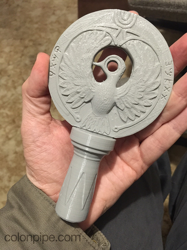
The headpiece of the Staff of Ra is from Thingiverse, and can be found here. The only change I made to the file before printing was to the medallion. For some reason, the medallion is oriented upright, which I suspect will not produce the best printing results. I split the medallion in two, and printed both faces of the disc laying flat, then joined them together. That way, there's no nasty overhang on the bottom of the disc, nor inside around the bird's head. There's also no need for any kind of support. The mounting piece below the disc printed very nicely, with a bunch of support around it.
My usual process with 3D printed items is to go nuts with 'filler primer' or 'spray putty', which is essentially really thick spray paint that you can sand easily. Generally, you add a couple of layers of the stuff, then sand or file it back. The trick with 3D printed objects is that you're only aiming to reduce the spray filler to the height of the 3D printed layer, so you're just filling in the gaps between the layers. Using a fine file or sandpaper on a block helps to do this. For an object that's supposed to look like cast gold, a lot of 3D printing artifacts and accidents will be forgiven.
The finish on the headpiece is Dulux Duramax Bright Gold paint. I've then gone over it with some brown acrylic paint, allowing the paint to sink into the crevices like ancient grime, then polished it back with a rag to reveal the gold again. This is usually as far as I go weathering any pieces, and I find it produces satisfactory results.
The jewel in the headpiece is a crappy red gem from a haberdashery store. Unfortunately, the gem isn't transparent, it has a reflective backing, but it still looks okay. Somehow, I don't think I would have been able to locate the Well of Souls with this headpiece, anyway.

Ark, straight from printer.
The Ark of the Covenant is also directly from Thingiverse. You can find the file here. The model looks great! I had some issues printing the cherubs on top, but thankfully the creator of the file has included a bunch of different options for printing the cherubs. Printing the entire lid, including cherubs, proved difficult as the cherubs are so awkwardly shaped that the entire inner part of the lid's surface was covered with support material, and the cherubs' wings ended up snapping off in the process of removing it. I ended up printing the cherubs separately, as well as using Netfabb to cut the filigree detail off the top of the lid piece, so I could print it again separately.
After several billion layers of spray putty and sanding, the Ark was also sprayed with Dulux Duramax Bright Gold.
The rods are wooden skewers wrapped with venetian blind cord, then painted a dark leathery red colour. Nothing fancy.
The remaining two items are my own creations.
The grail tablet was something I thought was going to be quick and easy. I had hoped I could model it in Strata 3D CX (a fairly obscure 3D graphics program that I use for everything, because I'm obsessed with using the wrong tool for every job), but things didn't go to plan.
I had planned from the beginning to use a heightmap to create the tablet. This basically means creating an image that has bright pixels where the high points should be, and dark pixels where the low points should be, then extruding the whole thing into a kind of topographical map. This is quite a common method for creating simulated terrain. I find it works quite well for organic shapes that don't have any overhangs, like the surface of an engraved tablet.

Unfortunately, Strata 3D CX's heightmap function just couldn't cope with the level of detail I expected from the grail tablet.
The first version of the tablet looked terrible. I had to trim some of the surface away, leaving horrible flat spots, and the Latin text, which is an integral feature of the tablet, only appeared as undefined pockmarks in the surface of the tablet.
This was not working for me.
Ultimately, I used heightmap2stl, a somewhat cumbersome command line Java application that converts a greyscale image into a 3D model using brightness data for height information.

Here, the image on the left is the greyscale image that was input into heightmap2stl, and on the right is the final file, after some tweaking and reducing and quite a bit of swearing, to be honest. BUT, the important part -- is that it looked pretty good.
I printed the model at 0.2mm detail, at 15cm along its longest edge (it's height, I guess). It printed quite well. You can't exactly "read" the Latin text, but you can see that it's text, and it looks great. I'm not concerned that the letters aren't very decipherable, because -- quite frankly -- it's Latin and I can't read it anyway.

The final item is the Chachapoyan fertility idol from Raiders of the Lost Ark. I wasn't satisfied with the level of detail or accuracy in the 3D files of the idol that I could find online, so I thought I'd try my hand at sculpting one myself.

Here you can see the progression from terrifyingly ugly formless blob of grey to terrifyingly ugly fertility idol.
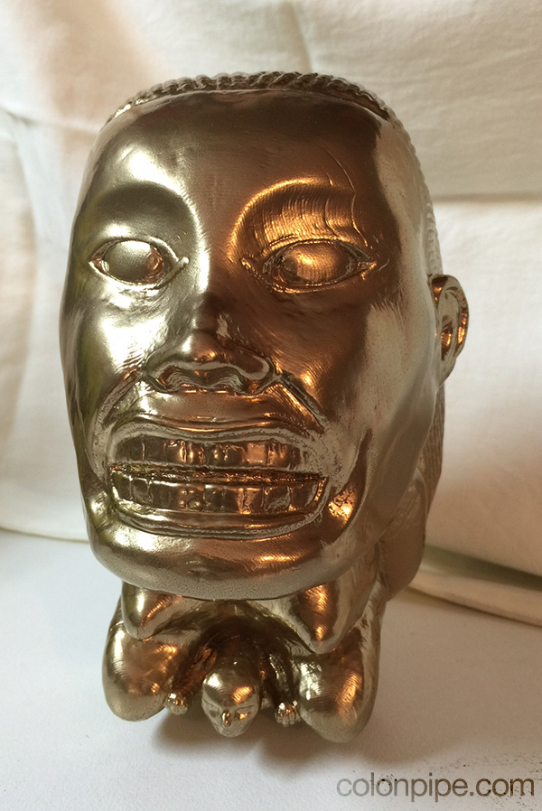
I then printed the thing as large as I could -- 17cm high, about 3cm shorter than the original prop -- and set about finishing and painting the idol.
I used the same process as above, filling and sanding until the surface looked as smooth as possible. There were a couple of printing issues on the idol, including a few spots where the layers had delaminated. These gaps still show on the final product, but I'm not losing any sleep over it. It still looks pretty good.
Now I just need to 3D print the grail, and some Sankara stones and a crystal skull and an antidote bottle and...

I bought a 19" Jakks Pacific Boba Fett action figure, because I thought it was good value for money. For $40, I have a 19" tall bounty hunter with reasonably accurate details. He's a little bit simple, but he's a good starting point for a repaint. Most of the inspiration for this project came from Cosplay Chris on YouTube, so, uh, thanks Chris. You do good things.
The plan was, basically, to rip Boba Fett apart, paint all the bits, replace the cape with something that looks less like a piece of muppet felt, and put him back together. And that's basically what I did.
Straight out of the box, Fett had a few problems that needed solving. Most importantly, he was missing his right shoulder bell. My plan to fix this was to attempt to cast a duplicate shoulder bell. Ultimately, I decided to do something a bit stranger, and go with the "poncho" look from the Sideshow Collectables Mythos Fett figure. This would mean I'd only need to find a way to make the cape and poncho look good, and not have to cast a replacement bell.
The other problem is much simpler: Fett's wookiee braids look like crud, as they're moulded into the plastic. I shall replace those with some kind of braided string or rope. Easy.

First up, pull apart and primer. Jakks Pacific toys are generally held together with screws and plastic tabs, and put up very little fight when assaulted with screwdrivers.
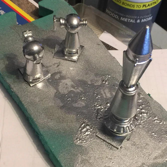
Chromed jetpack parts.
After taking the figure apart, I also used a rotary tool with a sanding barrel to remove the offending wookiee braids from Fett's chest piece. In the above photo, I've progressed to putting some dark blue paint onto the jetpack, too.
After that: Paint. This is the part where you'd expect I'd have taken a bunch of photos, but that's where you'd be wrong. Instead, we'll jump awkwardly to the completed paint job, and speak no more of it.

Well, we'll speak a little bit. I repainted the armour in three layers. The design of Fett's armour suggests that various parts of the armour were originally different colours (specifically yellow and blue) underneath, before they were painted green. The metal also shows through in several places. I tore up bits of masking tape to mask off the areas that would be chrome, then used larger pieces of tape over the chrome areas to allow another coat of "original" paint (yellow or blue), then larger pieces of masking tape again before the final green coat. I ended up covering up the printed logos on Fett's chest, but I figured the poncho would cover those areas, anwyay.
As usual, what I thought would be the final paint...wasn't, and required considerable weathering. I was unable to find an appropriately light grey for Boba's shirt, so I ended up using white in the hopes it wouldn't be blindingly clean, but it was blindingly clean. So, I shall weather the crap out of it with some airbrushed dirt.

There's the final paint job, with weathering on the white shirt and a whole bunch of darkening and dirtying on his boots, pants, gloves and pretty much everywhere else. I've dry-brushed a lot of chrome paint along the edges of the forearm parts, and on the kneecaps and shoulder bell, and generally weathered the hell out of all of the metal parts.
The wookiee braids are now some pieces of braided rope, which I've distressed with a wire brush.
The cape and poncho are some pieces of cheap fabric that I've also distressed with everything I could get my hands on. One of the best techniques I found was to scrunch the fabric up tightly into a ball, then wedge it into my vice very tightly and proceed to smash it quite violently with everything from a hammer to a wire brush. The cape was airbrushed along all of the edges to suggest dirt and grime.
I think the poncho still needs more weathering.
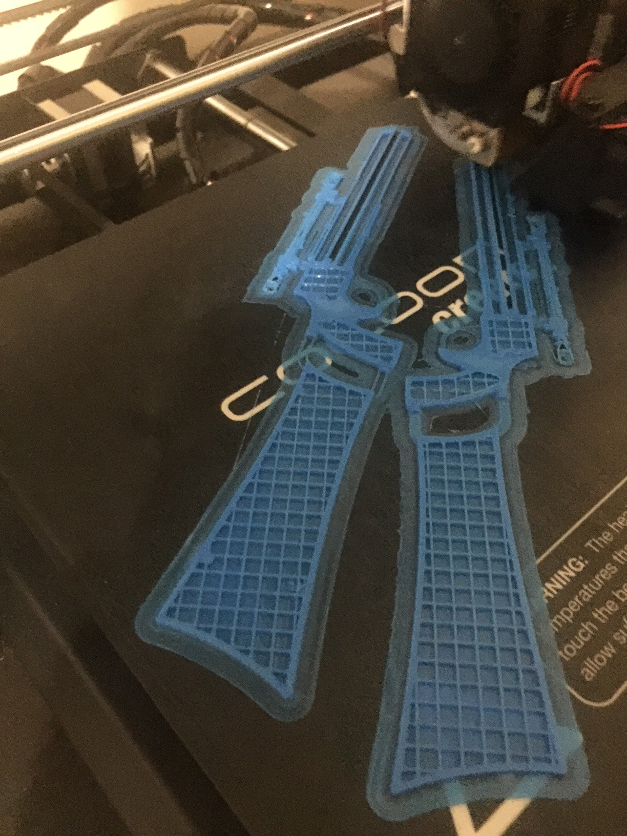
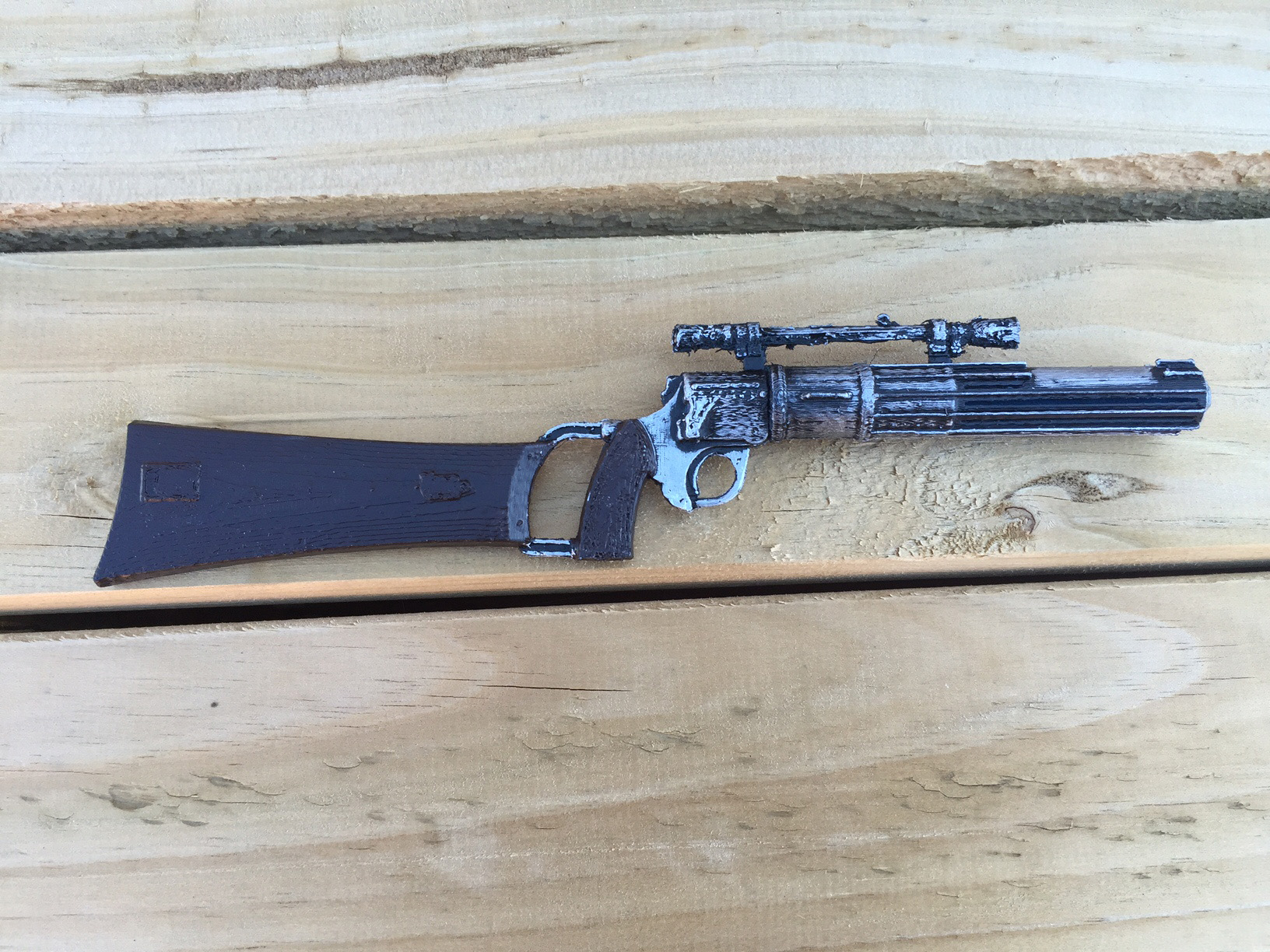
For one final detail, I 3D printed an EE-3 Carbine rifle for him. I found the model on Thingiverse (there are several) and set it to print. The printed piece was painted matte black, then the butt was painted brown and some silver Rub'n'Buff applied to the metal parts.
I will, one day, add a strap to the rifle so it can sling over Fett's shoulder.
I'm in no hurry, though.
Heyhey. So yeah. This isn't a "how to" guide, or a tutorial, or any of those things. This is just a bunch of photos of what I did to make a model of R2D2 using a few things from Bunnings and some junk I had lying around.
If you want more info, feel free to drop a comment, and I'll try to remember what I did.
Some quick background: This project was part of a challenge with a colleague, wherein we both foolishly decided to construct R2D2s, pretty much to the same scale, and with pretty much the same materials and intention. I'll talk a bit about where our techniques and materials varied, and why, and I hope to provide a photo of both finished products toward the end.
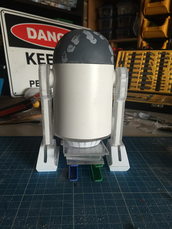
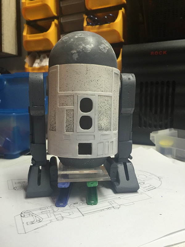
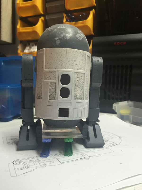
Let's start with the best and worst part of making R2D2:
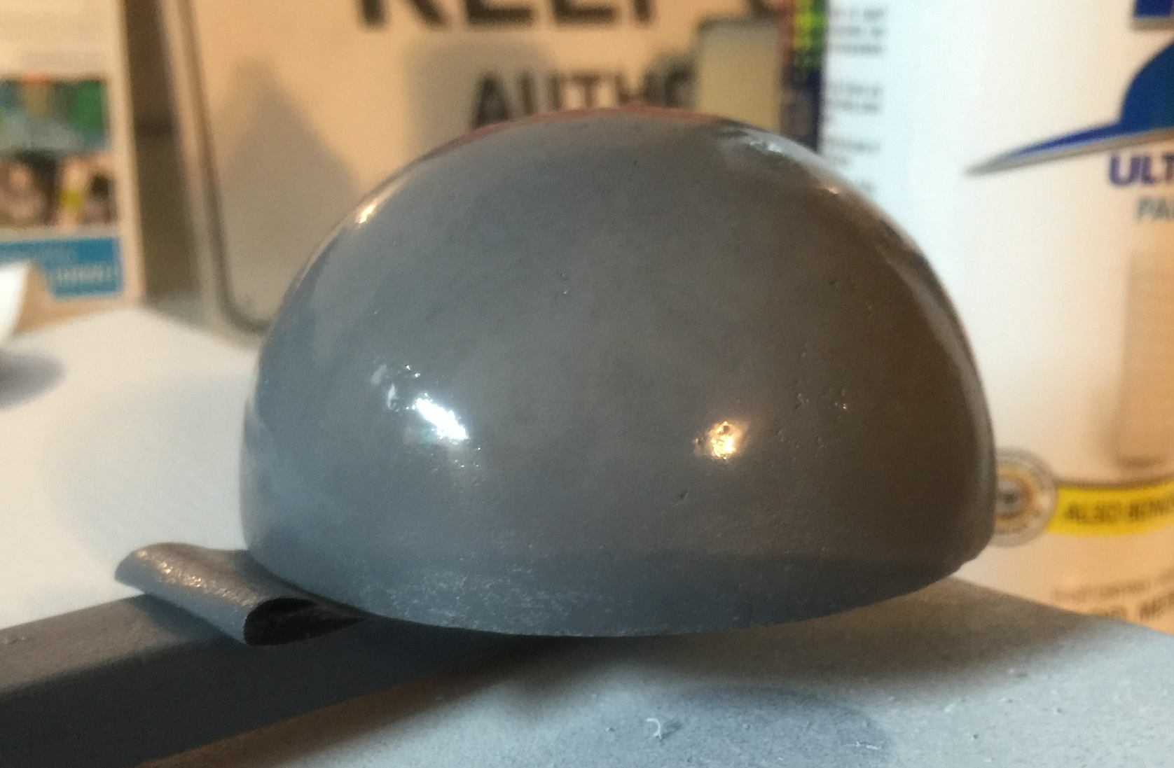
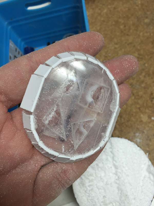
Oh, god. The dome. My first piece of advice, if you ever attempt to build an R2D2 of any scale, is to find a dome first. Find a good dome. Find a nice, structural dome. If you want to build a full-size droid, IKEA has a pendant lamp for around the $100 mark that's perfect. If you're going for something smaller, try a ball, or a Christmas bauble. My colleague chose the Christmas bauble path. I didn't.
I, foolishly, decided to tailor my dome size to the size of PVC tube I had intended to use for the body of R2. This meant I was on the hunt for a 75mm dome. And I struggled to find one. I found Christmas baubles in the 78mm range, but I was stubborn, and ultimately chose a very labour intensive and unsatisfying way to make my droid head.

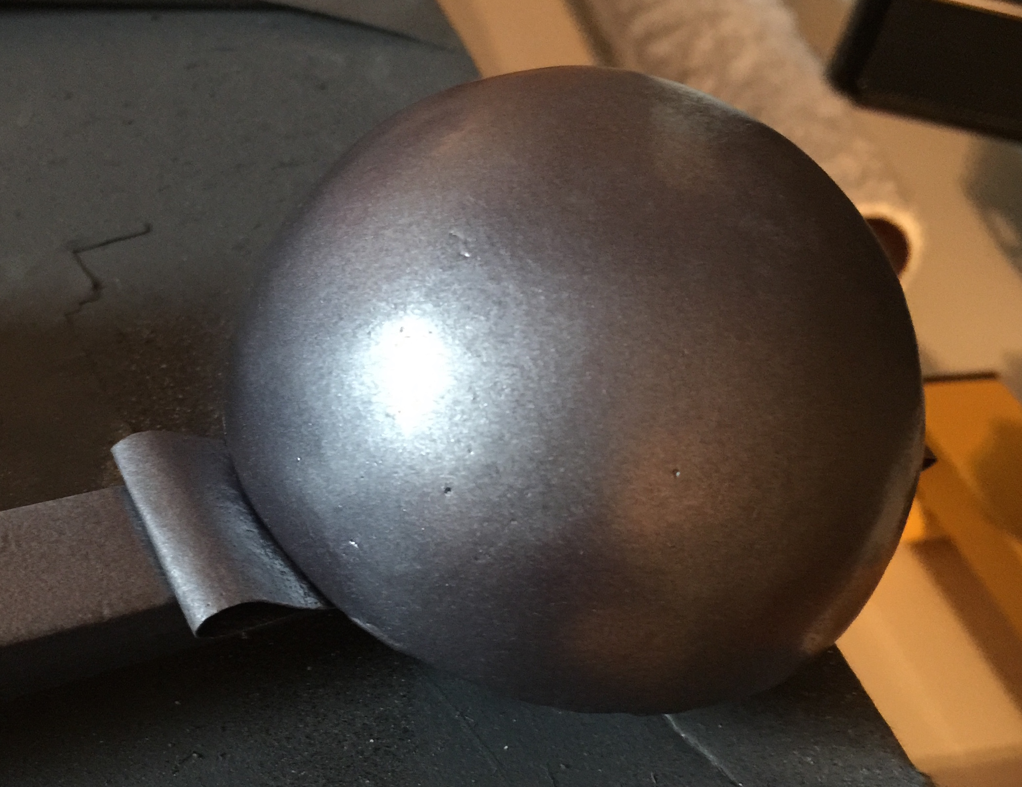
That...thing...that you see above is a styrofoam ball from Spotlight with the initial layers of a shell being built over it. The shell is made from liberal dousings of cyanoacrylate (super glue, and in a well-ventilated area, I might add) and sprinklings of baking soda. After about a bazillion layers of glue and soda, I ended up with an eggshell-thin dome supported by soft foam, and ultimately filled with every kind of plastic bog and putty I could find. Was I satisfied? No. Will it do the job? It'll have to, for now.
My advice? Christmas bauble, next time.
So, we're going to continue to talk about how to make a dome the hard way. This was a long and tedious process, and I feel it's only fair that you should have to suffer through a proportionally painful part of this process, much like I did.

That's after about three days (not full time, of course), of sanding and patching and filling and sanding and patching and filling.
Above is the net result after a bazillion years of sanding and filling and puttying and sanding and priming and swearing. It's almost there. There are still a few holes and scratches to work out.
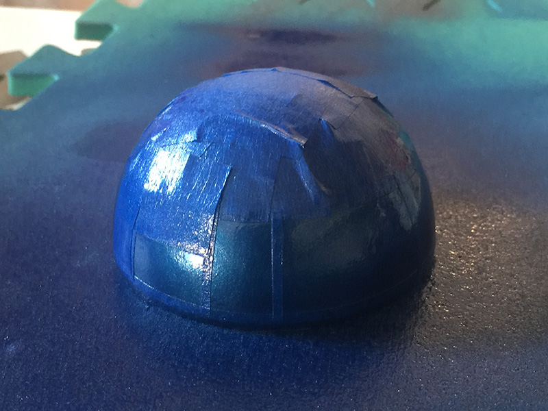
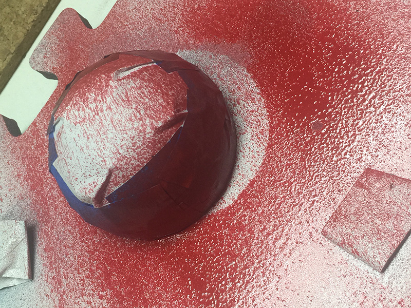
And now with a coat of silver (not chrome) paint. Still a couple of holes I hadn't noticed. They'll get filled, don't worry.
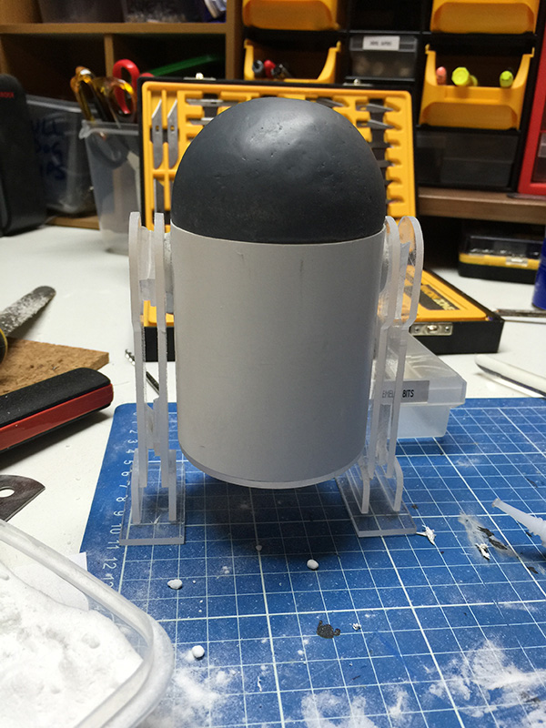
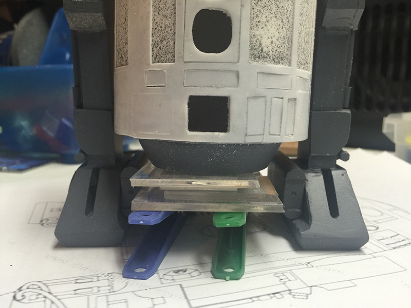
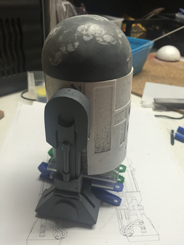
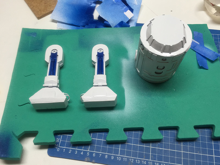
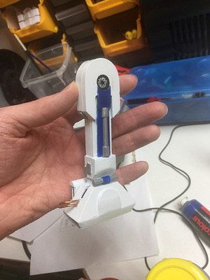
Having now made a somewhat satisfactory dome (albeit without any detail, yet), it's time to do something with the body and leg assemblies.
I don't have a lot to say about these parts, other than they just worked. Not a lot of planning, and fairly minimal measurement went into making the barrel. The legs just kind of fell into place.
R2D2's legs are made, mostly, from acrylic sheet. I love acrylic sheet. It's easy to work with, it doesn't mind being sanded and filed, it takes paint and glue with ease, and if you need something to be transparent, it's natural state is...transparent. For R2, though, acrylic's defining quality was structure. I built R2D2's legs using a rough template that I printed off the internet (I believe I searched for something along the lines of "r2d2 plans" or "r2d2 blueprints" and found many satisfactory examples).
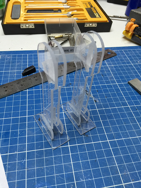
One of the most terrifying parts of this project, at least for my humble self, was the fact that R2D2 is essentially symmetrical. I hate symmetry. I hate making two of something. I hate building things where the left hand side has to match or mirror the right hand side. R2D2, unfortunately, has two legs. And they're both largely the same. As I said earlier, the legs just worked. I have no explanation or solution for making two droid legs. They just happened perfectly the first time. It's both exciting and disappointing simultaneously.
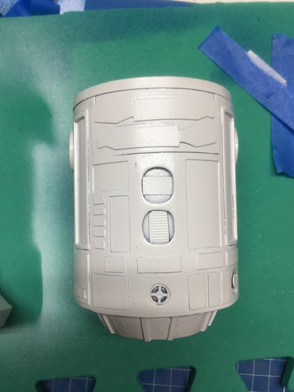
R2D2's body is also not a particularly complicated thing, being that it's essentially a cylinder. There are a few details that will need to be added, but the bulk of the work is done once you've cut out an appropriately-sized chunk of PVC pipe and built some kind of shoulder apparatus for the legs to attach to.
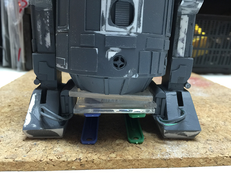
The first photograph above shows the tapered protuberance that goes underneath R2D2's body. This is the part that would have a rectangular hole to receive R2's third foot in its retracted position, but I had already decided that my R2D2 would be bipedal and I had no intention of constructing the third leg. We'll pretend the third leg is inside there, somewhere.
I chose to make the tapered part by stacking acrylic pieces (and scrap pieces), then smoothing the tapered sides with styrene sheet offcuts and filling with cyanoacrylate and soda or plastic putty. Ultimately, this was -- as usual -- the most difficult way I could possibly make the part, and my colleague chose a much simpler solution: utilise the already curved edges of the PVC tubing, and with about four cuts, make the shape and stick it together.
The last four photographs above also show R2D2's feet with their initial covering of styrene, giving the appropriate shapes for the battery and cable mountings and a reasonable representation of the angular sole of his feet.
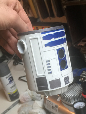
Next up: Detailing the body.
The next step in the arduous process of creating an Astromech droid is to get some detail onto its chassis. Again, to the internet, and with the digging up of blueprints. I managed to find a nice wraparound graphic of the panel locations on R2D2's torso and back, and scaled them appropriately to be able to stick them around my piece of PVC pipe.
To create the raised texture of panels, I used a sheet of 0.5mm styrene, cut to size, to which I adhered the wraparound print with spray adhesive. After cutting out all of the little panels, I had a lacy mesh of plastic to glue to the front of the droid. For the most part, this was pretty successful.
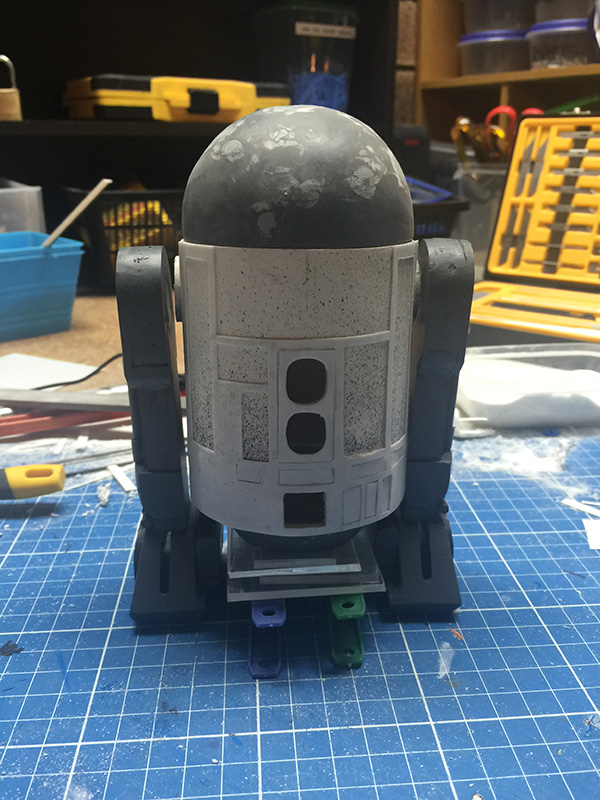
You can see by this point I've also added additional detail to the leg pieces, including some styrene strips to add panels and shape to the top of the shoulder and hub, and some pieces of Chupa-Chup stick for the pistons.
The vent at the bottom was made from the top of the lid of a gel pen, which happened to have a nice four-pointed configuration. I wish I'd created the rear vent first, as my second attempt at plastic welding the cap in place ended up straighter and with a far superior finish.
The battery boxes and cables are in place, now, also. The batteries are made from a couple of lids from USB sticks, and the cables are just audio cable from a car stereo.
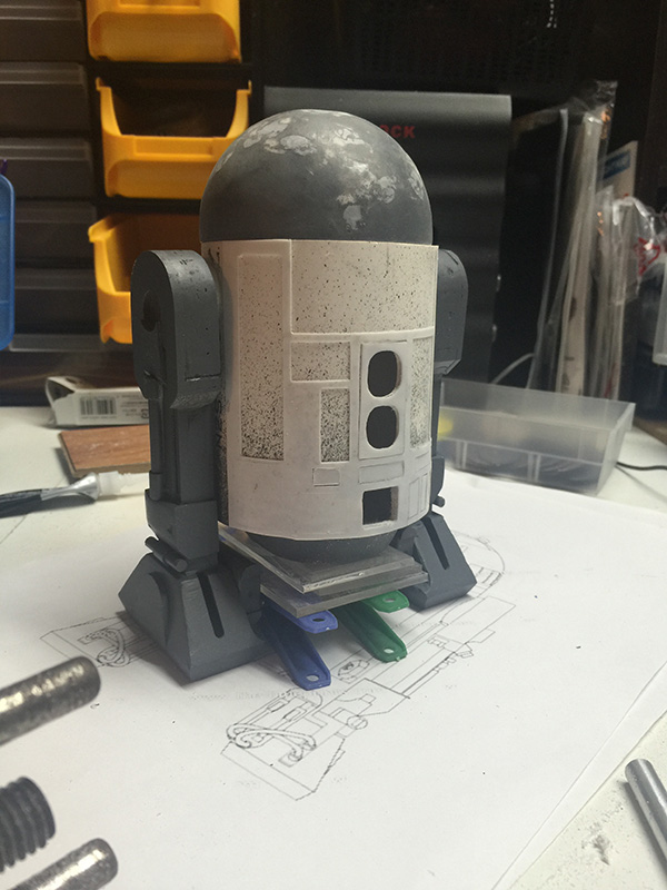
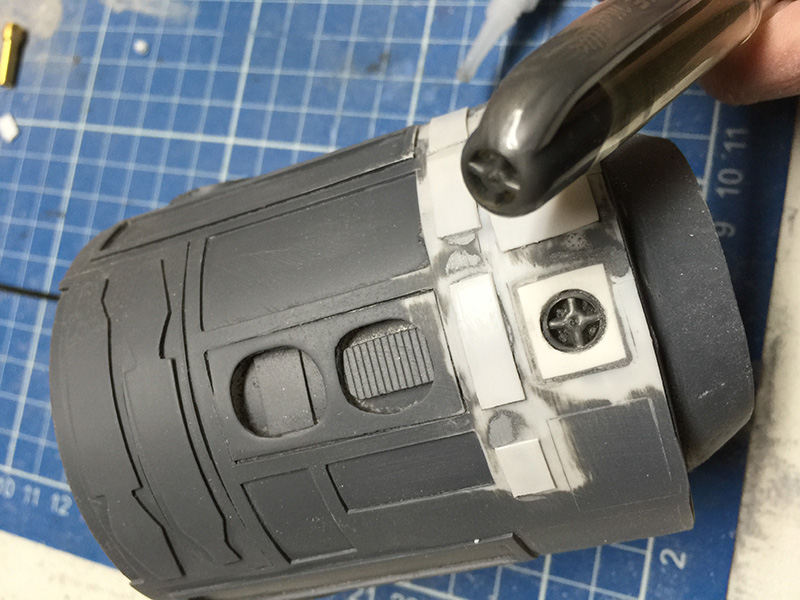
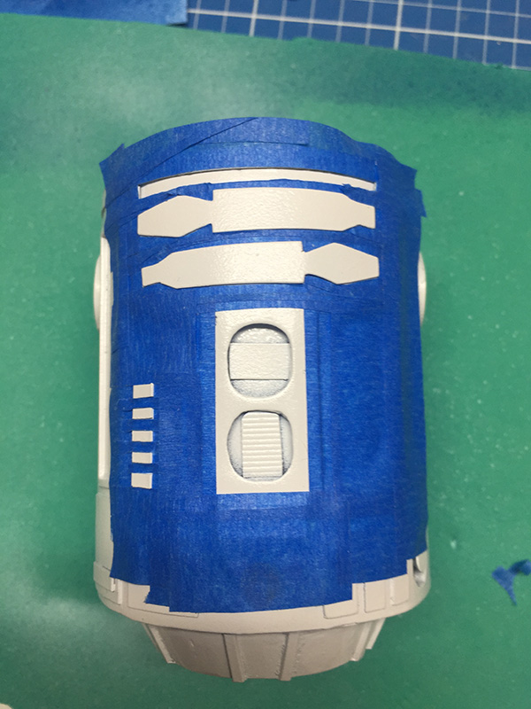
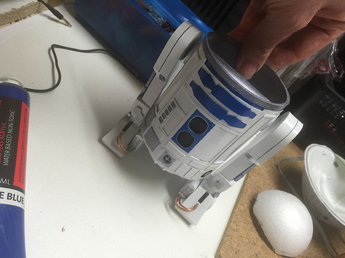
Next up: Dome details, and lets start painting!
Alrighty, it's time for some:
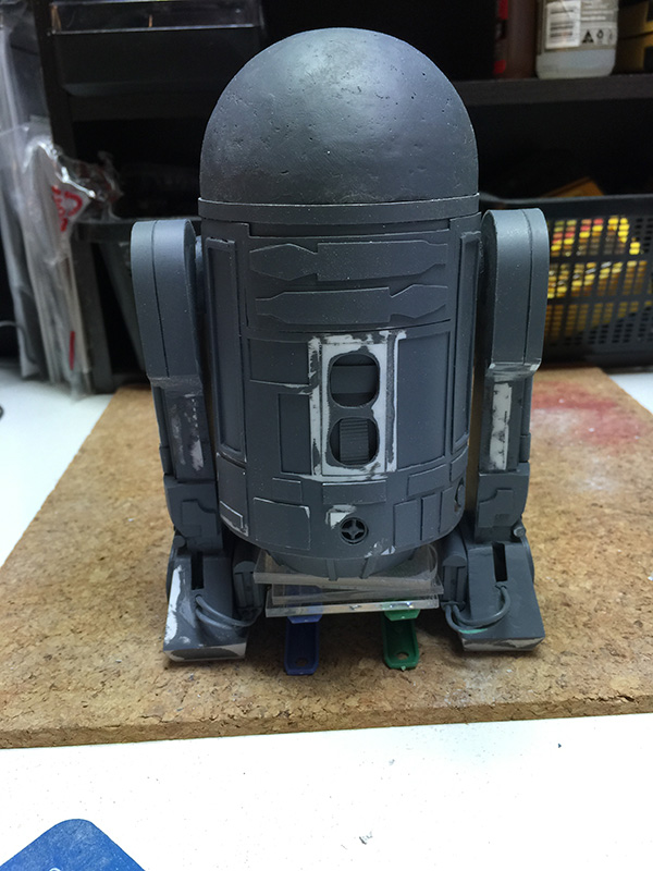
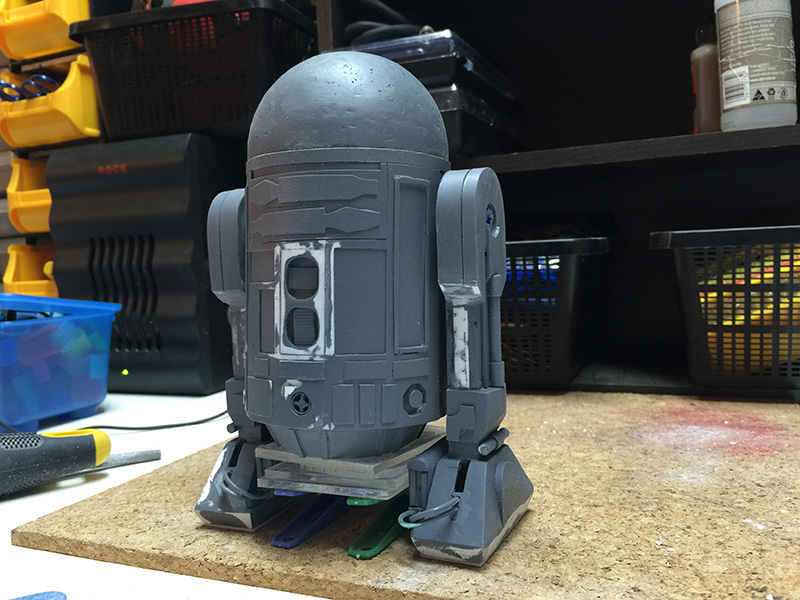
There's not a great deal of add-on details on R2D2's dome. There's an eye in a little square-ish mount, three holographic projectors, and a bunch of painted-on details.

The eye surround was cut from the Christmas bauble that I had determined in the early stages was far too large to use for the dome proper. As the eye frame is essentially a chunk cut from a dome of a larger diameter, the Christmas ball turned out to be perfect. The little lip at the bottom, and the structure underneath to give it some height were all cut out of styrene offcuts and attached with cyanoacrylate. I don't have a photograph, but the hole for the eye lens was made with a drill.
"Help me, Obi-wan Kenobi. You're my only hope."
R2D2 has three holographic projectors that protrude from his dome. They're all pretty much identical, and consist of a tubular lens extending from a sphere that allows the projectors to point in various directions. I had no intention of replicating the directional ability, but the basic shapes were essential.
After a few experiments with various beads and baubles, I stumbled upon.....push pins.
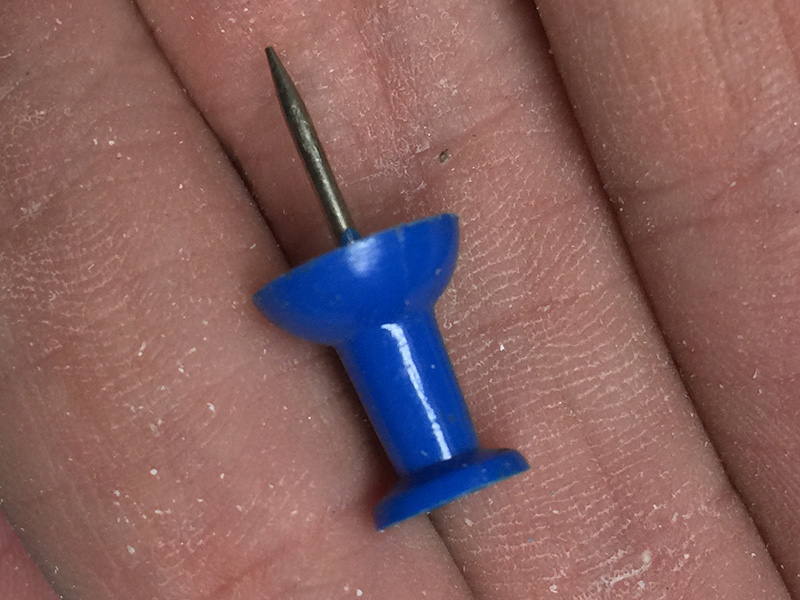
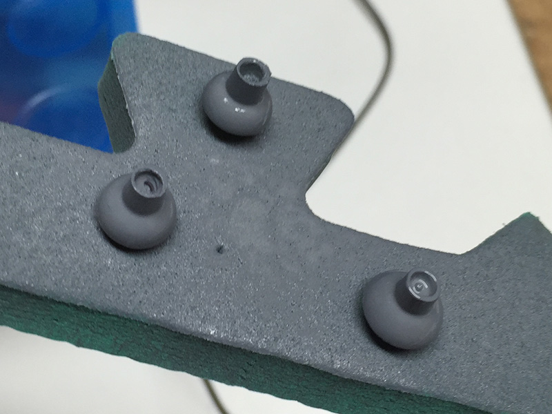
By cutting the flat end off, and drilling out the stem, the push pins resemble the holographic projectors pretty well! After drowning them with primer, they got chromed and put aside to be attached to the dome after the panels get painted.
Up next: Painting the barrel and legs!
Okay, time to slap some paint on this thing.
Getting the painting process started wasn't difficult, and involved slapping a couple of coats of primer onto R2D2's body, then a few coats of appliance white high-gloss paint.
My strategy -- as is often the case -- is to try to achieve something kind of "showroom new", but if it fails, I have the backup plan of slathering it with weathering. So, Plan A for R2D2 is a brand spanking new droid, and Plan B is something along the lines of R2D2 after being rescued from the swamps of Dagobah.
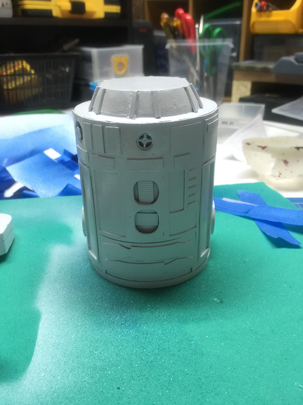
It was easiest to paint the body upside-down, as the top (where the dome will attach) obviously does not need to be painted.
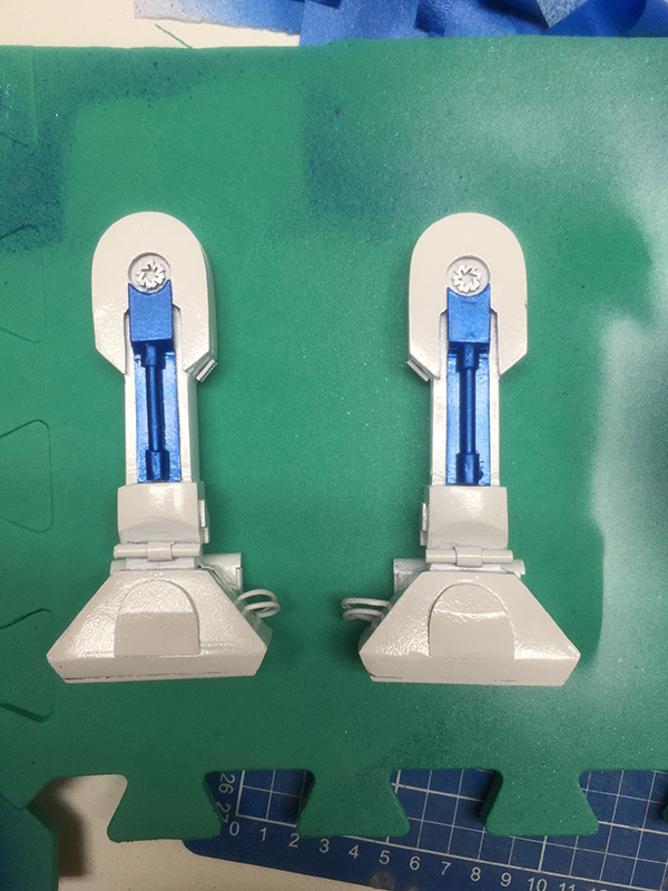
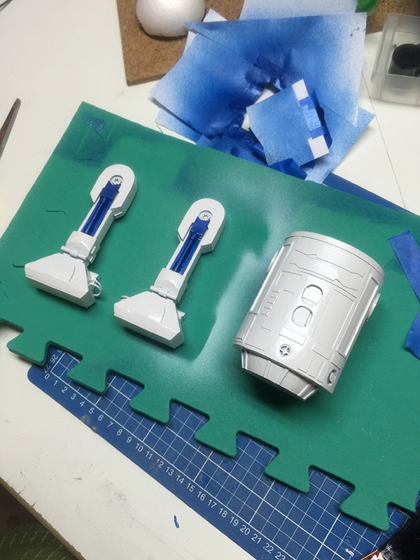
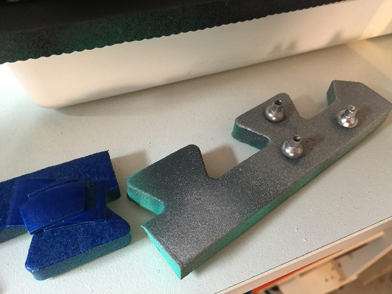
Next up, some masking, and some blue paint on the legs. The pistons on the outside of the legs will eventually be brush-painted silver, and some other details will be tidied up.
You can see some of the details on R2's legs, with some silver paint on the shoulder hub and some copper paint for the battery cables.
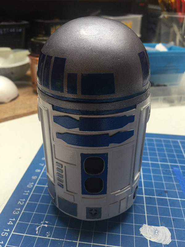
Still some more details to go.
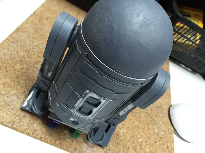
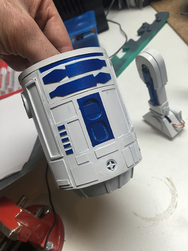
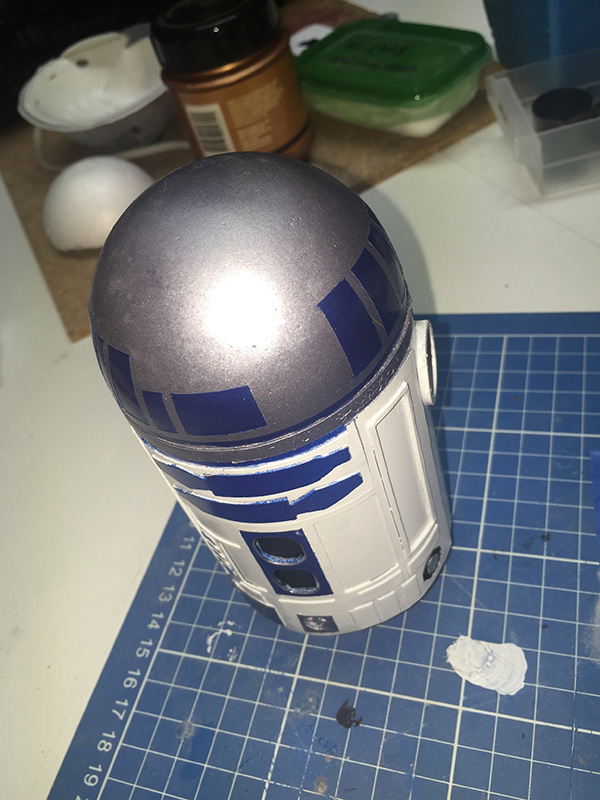
So, continuing on with details on the body.
After much masking and swearing and touching-up and regret over choice of parts, I managed to get the majority of the details on the front of the droid completed. I made some executive decisions about which areas would get detail and which would not. In particular, I kind of regret deciding not to further detail the lower-left silver panel, which on the prototype droid has a bunch of air gaps. Oh, well. Maybe next time.
The leg now has some chrome (silver, really) detail on the piston and the hub (which is made from a slice of a wall plug) and some silver and blue details on the foot...rod...thing. I ended up using blue acrylic for the band around the rod, as the metallic blue I've used on the rest of the droid doesn't decant from the aerosol can particularly well.
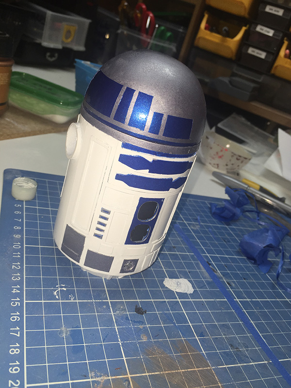
Next time: Lets put a dome on! This thing's almost complete.
And now, some dome details.
Did I mention dome details?

So, from left to right, we have:
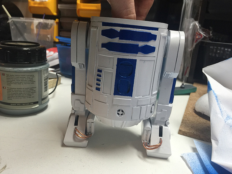
Next up: Assembly and completion!
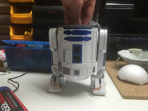
So, all that's left to complete R2D2 is to basically stick all the bits together.
A bit of glue and swearing later:
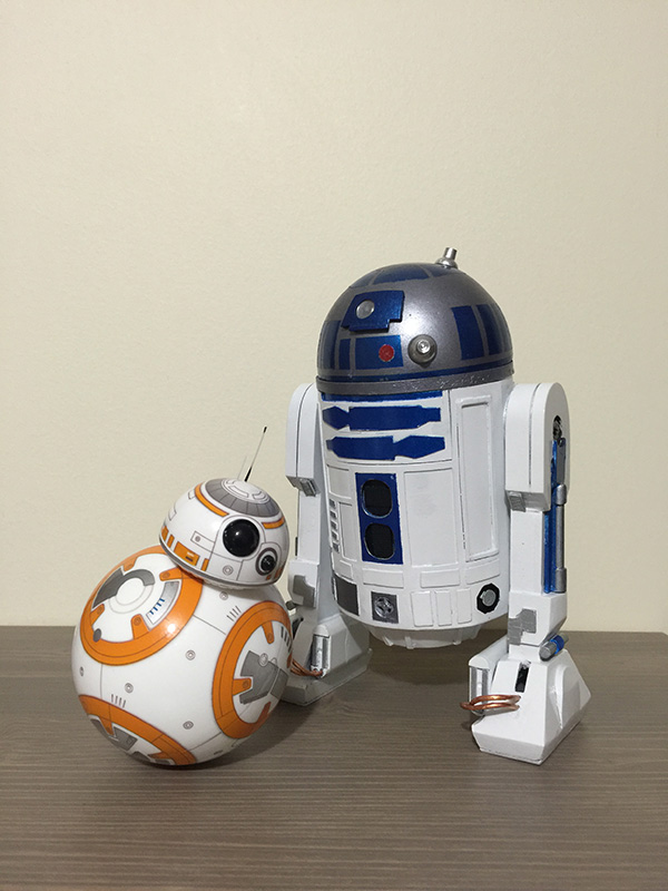

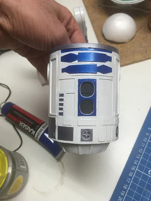
Above we have R2D2 with the Sphero BB-8 autonomous robot toy. I didn't plan it (largely because the Sphero toy wasn't available when I started the R2D2 project), but they ended up pretty much exactly the same scale. That's kinda nice.
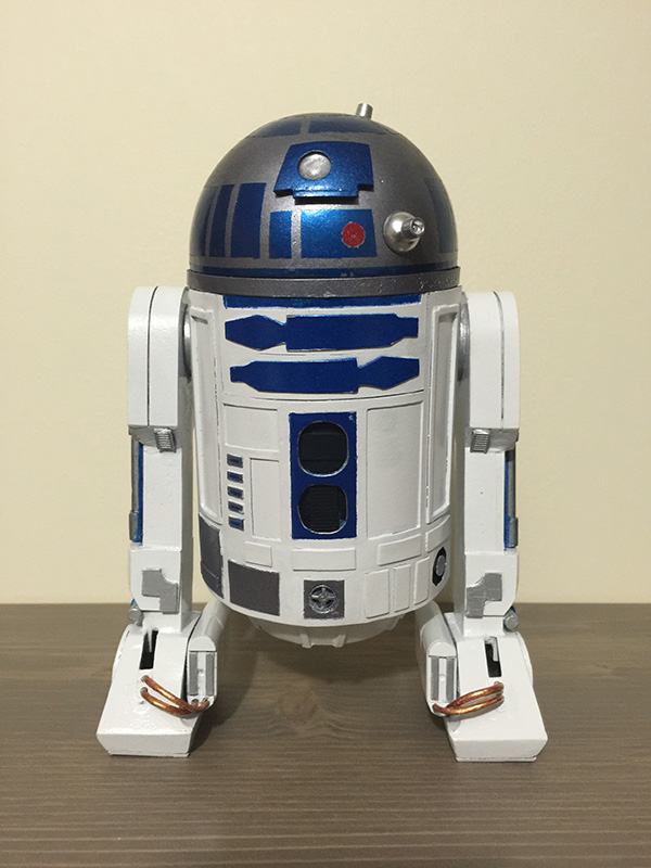
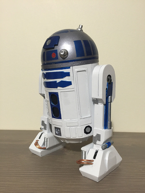
I'm happy with the level of detail I managed to incorporate into R2D2.
This is one of those things everyone should do. Everyone should own a lightsaber, and everyone should -- ideally -- build it themselves. This is my version of Darth Vader's lightsaber, built from PVC tube and various bits of junk.
Enjoy.
Step 1: Search internet for blueprints and dimensions. This is not difficult. I'd suggest searching for something like "darth vader lightsaber dimensions", or such. Use your imagination.
Step 2: Figure out your scale, if you need to. I have PVC tube in 42mm, which is awfully close to the 40mm barrel the original Graflex-style hilt was built with, so I'm pretty content to go with that, and I chose not to adjust any of the other dimensions, as two millimetres didn't seem enough to bother with.

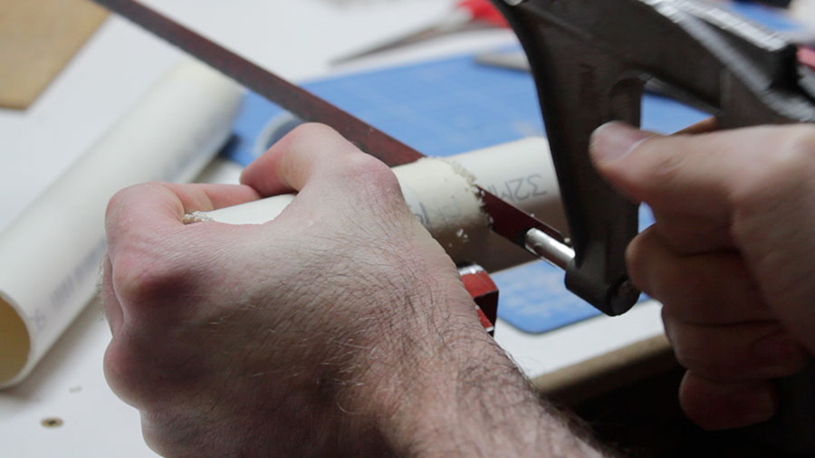
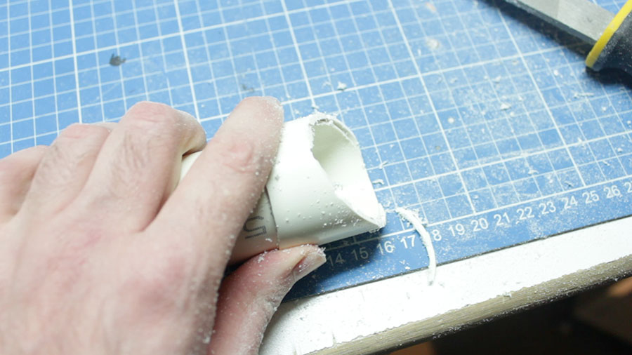
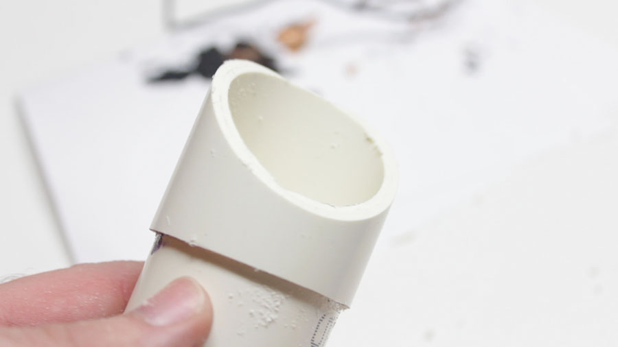
Step 3: Cut the tube to the right size and cut the end off at the appropriate angle. A mitre box, or a mitre saw/drop saw/compound saw/whatever would probably be cool for this. I didn't have any of these things handy, so I just marked the end and hacked it off with a hacksaw with plenty of plastic to spare and set about filing it down to the correct marks.
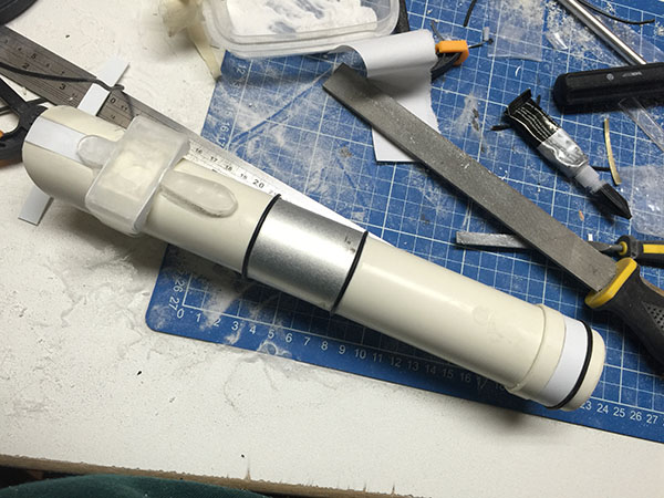
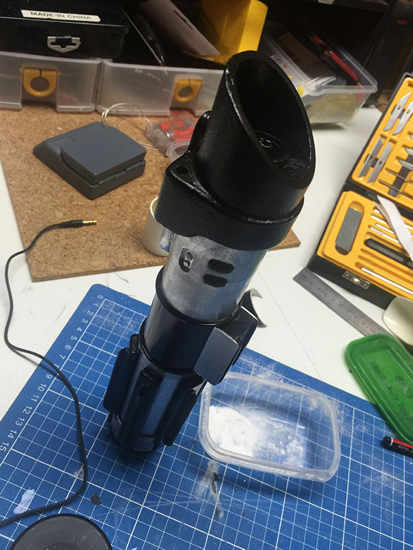
Step 4: Vader's saber has an extra-thick cowling around the emitter with a rectangular box on the side. I made the thicker cowling by adding an extra piece of 42mm PVC tube around the outside of the main tube.
Again, I knew I would make a total balls-up of the angled cut, so I hacked it off with some PVC to spare and filed it down to make a "machined" edge. There you go, a double-thickness cowling.
Step whatever: There's an additional band at the base of the cowling, which is thicker again. Same process. This bit requires an extra part cut out, as it flares toward the switch side of the saber.
File it.

Mark the bit to cut out.
Cut out said bit, and you've got the beginnings of a saber emitter cowling.

Step orange: The various layers and thicknesses of PVC create some pretty ugly gaps. Only one of these needs to be fixed with any real quality, the rest will get covered up by the rectangular box contraption we're about to build.

This is clear acrylic. Clear acrylic is awesome. It's awesome for a bunch of reasons:
To make the rectangular box on the cowling, I layered various bits of acrylic and styrene, and did some incredibly rough filling.
Another piece of acrylic, this one measured to be the diameter of the triple-layered PVC tube it's sitting on top of. It should be exactly the width of the tube. This is important. Kind of.

Join the whole thing together, and fill and sand until it doesn't look like crap. What I've done here is pretty much make a box, using scrap acrylic and some odds and ends of styrene sheet. I like using styrene sheet for the parts that don't necessarily need to hold much weight, or are only decorative. It's thin, but it looks solid when it's all painted and good to go. My adhesive of choice for this project is super glue, and lots of it. Super glue can be accelerated by using bicarbonate of soda, which:
It's essentially magic and witchcraft. And it's awesome.

Step parsnip: Make rectangular box look decent. My approach to this is to add layers, then sand back, then add layers, then sand back. Superglue and bicarbonate of soda is pretty much the undo button of sculpting and carving stuff like this. Screw it up? Add more. Too much? Sand it away. Just don't breathe the fumes or stick any important parts of your body to things you don't want them stuck to.
Here I've also filled the channel at the top, where the cowling tube splits apart. 1mm styrene sheet and some superglue and baking soda. Perfect.

Sanded and pretty much finished.
Step squeeble: This is three layers of acrylic glued together in a vice, getting filed down to be the little control panel on the top of the saber.

Step 1,493: Build control box and clamp details. The clamp strip is a piece of sheet metal from a clothes dryer duct, which happens to be awesome for lightsaber clamps. This is why you should never throw away anything that looks like it could be useful.
I didn't document building the control box, as the process was pretty much:
The ends of the clamp strap are detailed with some AV wiring. This is sometimes a mistake, as some kinds of paint make the rubber insulation on electrical wiring sticky, and they never stop being sticky. In this case, I appear to have dodged a bullet, and the wires remain stick-free.
Progress so far, and a messy work area. I've used similar techniques to build the end cap on the other end -- cut and split some PVC tube, add detail using styrene, and a piece of AV wiring for the rounded detail.

Step weasel: A coat of primer usually identifies all of your flaws. There are some chunks in the PVC pipe that will need filling and sanding. Here, I've cut two out of the six vent holes in the casing. I ultimately decided to only cut four -- two on each side -- as I was happy with how the outer four holes looked, and I had some concerns that I would not get the inside two holes perfectly aligned. I'd prefer it looks properly made and inaccurate than accurate with flawed construction. Things like that annoy me.
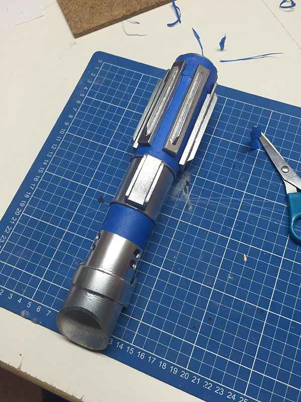
Step SILVER: Chrome the hell out of it. Here, I've coated it with a liberal lashing of Krylon classic chrome, and am in the process of masking out the black parts to be hit with some glossy black.
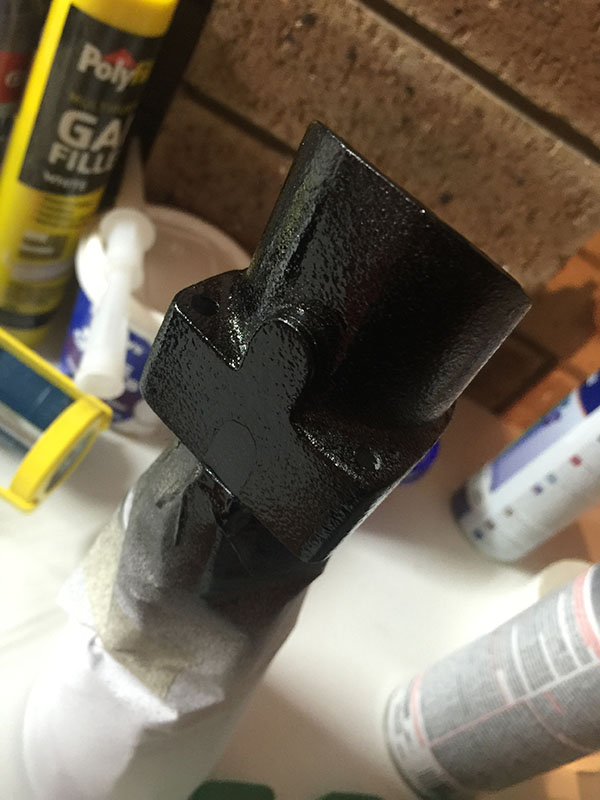
Step BLACK: Here's the black. I made the executive decision to make it a fairly thick coat of black, as the paint that I have tends to decide on its matte level based on how thick the coat of paint is, and I wanted this to be as glossy as possible. If you take this stupid approach, be sure to hold the painted object by hand and move it around a lot, so any drips don't kind of well up in the low points and screw the paint job entirely. After much gyrating and swearing, the paint finally dried enough to put the thing down.

Step Gary Glitter: Now we're getting risky. I knew Darth Vader's saber had a weird kind of cast-iron effect on the emitter cowling. It's lumpy, and very, very matte black. I originally planned to use granite-effect spray paint to achieve this, but the stuff is expensive and I didn't want to waste money on something that might not work. So I wasted less money on something that might not work.
For half the price of the granite paint, I managed to find some glitter paint, which also imparts a texture to whatever you paint with it. Turns out the vile shite is just particles of glitter suspended in clear varnish, which, when sprayed, spit in all directions like a hurricane of shiny snowflakes and proceed to stick to everything. Given that glitter has a propensity for sticking to everything when it's in its natural state, this combination is truly terrifying.
Regardless, I masked off the end of the saber and coated it three times in Rustoleum glitter paint.
GLITTER.

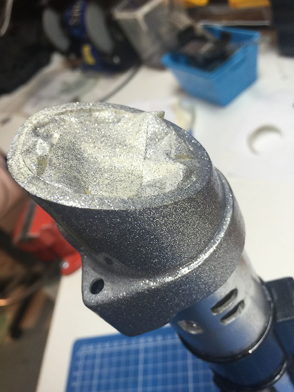
Step farfalarganfarful: While waiting for the umpteen coats of craft herpes to dry, I started building the emitter's internals. These did not turn out as detailed as I had hoped, as I was a) impatient, and b) running out of useful parts. I ended up making a wee cylinder to stuff down the end, by cutting some PVC tube and splitting it so I could reduce its diameter, then cutting a disc of acrylic to go in the end. The detail on the emitter is a smaller piece of PVC tube, and the end of a wall plug. High tech.
The ring should really be larger, but it's all I had lying around, and I usually have zero patience when a project is nearing completion. You can see the end of the saber hilt in the above image, too. I added an additional strip of corrugated styrene to the very end, giving a kind of grip-like appearance to the endcap. It looks awesome drowned in chrome paint. (Lets face it, everything looks awesome drowned in chrome paint.)
Step flurple: This is the switch, which is made from three pieces of acrylic glued together and clamped, then filed within an inch of its life until it resembled the switch from Vader's lightsaber. I drilled the 4mm hole starting with a .5mm bit in my Dremel and progressively scaling up the bits, so that I could be reasonably sure the drill wouldn't wander and end up making a stupidly off-centre hole, or something. One of acrylic's best features is that it drills really, really nicely.

Primer on the switch. Yes, there's a gouge in it. No, I don't care. Life's too short for that kind of thing.
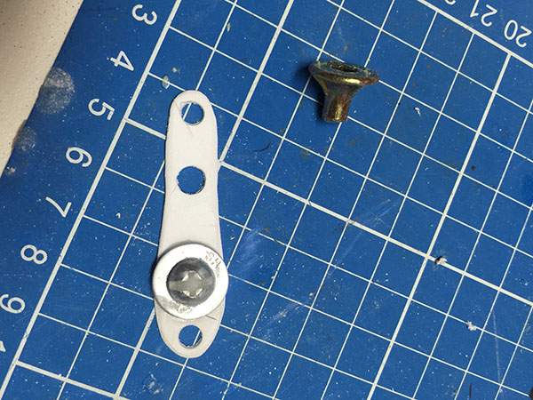
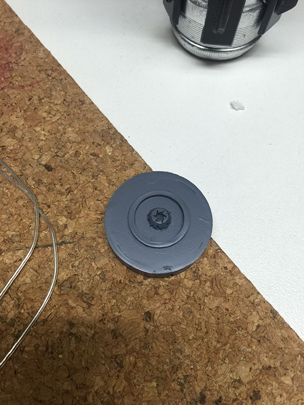
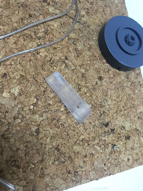
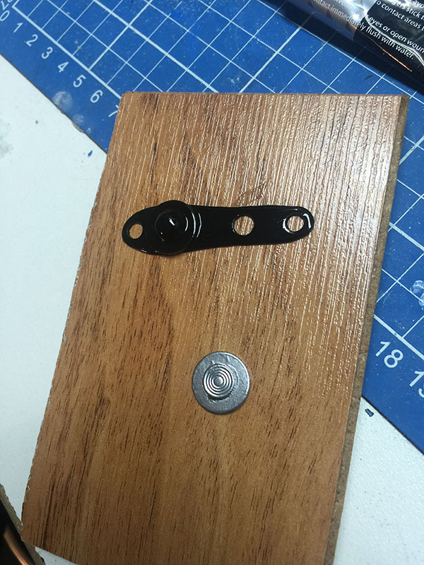
Step eleventy squillion: Details to go on top of the saber. The plastic shape is styrene, designed to fit over the acrylic extrusion I made earlier. On top of it is a washer and a screw, the head of the screw is filled in with superglue and sodium bicarbonate so that it doesn't look like a screw anymore. The bugle-headed plasterboard screw will substitute for the flanged....dial....thing...on the top of the saber. It's kind of the right shape. I'm getting impatient, here. I ended up sticking a washer on top of the bugle-headed screw and filling the washer's hole with superglue and soda, just to disguise it obviously being a plasterboard screw.
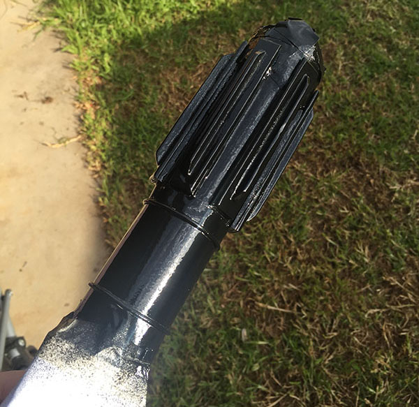
Step boo-urns: One of many coats of super-flat black spraypaint on the saber cowling. The texture from the glitter paint shows through quite nicely.

Texture ahoy!
This is starting to look a bit like a lightsaber. The emitter is now in place. I've also built some grips for the handle. They're nothing elaborate -- flat pieces of acrylic, some with the edges smoothed out, some with some angular corners. I didn't take photos of the process. I'm sorry.

At some point, I've also put some flat pieces of Styrene painted with Krylon classic chrome on the sides of the control box.
Step AHOOGAH, AHOOGAH: Some more details. The knobs-and-buttons thing makes a re-appearance, this time with paint. I thought I'd made a tragic mistake by painting the bizarre styrene shape with spray paint (and primer), because it started to eat the styrene and the whole thing ended up turning to glue, but something weirdly fortuitous happened: It just rounded the edges off perfectly, leaving a really nice gloss finish. So, uh, yay. Or oops. Depending on how you look at it.
Bottom bit is a washer with the head of an upholstery nail attached.

Washer/nail combo ended up on the side of the control box, here, where it serves some purpose best known to the Empire.

Step doobly-doo: The small bolt/knob at the end doesn't look a great deal like the original, but it does the job. For this, I used a piece of acrylic rod from a paintbrush handle and lathed it in a drill with a rounded file to create the shape. I didn't document this process as I was concerned that I could die if I was distracted whilst lathing a piece of plastic wedged in a drill, wedged in a vice. Perhaps next time.
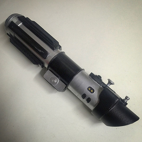
The finished product. A reasonably accurate version of Darth Vader's lightsaber. It now lives in a cabinet along with a bunch of other junk.
Hooray!